


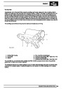


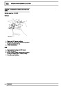


ENGINE
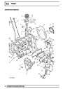
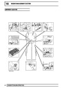
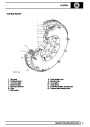
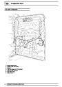
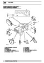
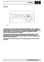
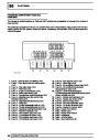
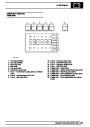
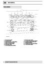
CYLINDER HEAD COMPONENTS
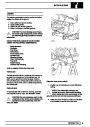
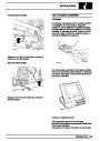
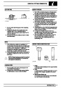
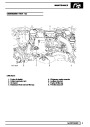
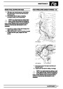
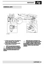
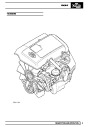
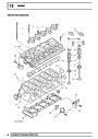
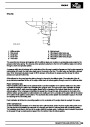
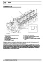
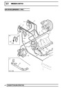
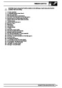
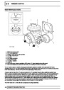
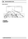
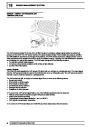
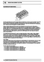
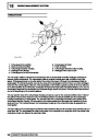
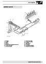
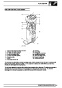
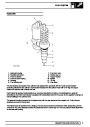
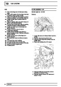
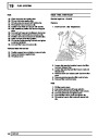
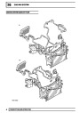
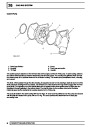
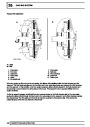
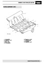
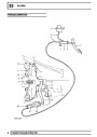
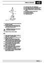
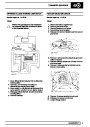
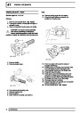
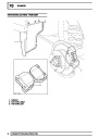
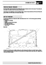
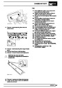
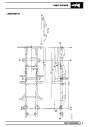
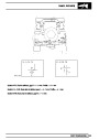
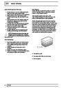
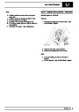
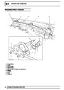
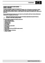
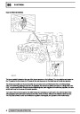
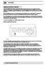
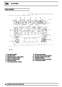
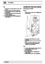
The cylinder head components are described below:
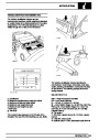
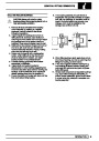
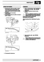
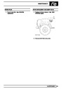
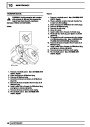
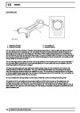
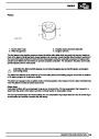
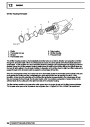
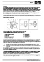
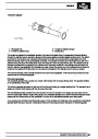
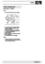
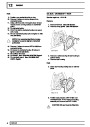
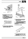
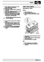
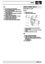
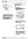
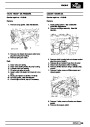
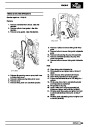
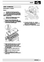
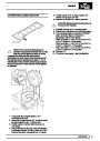
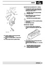
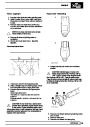
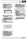
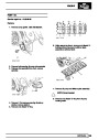
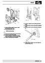
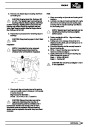
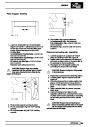
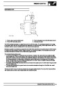
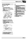
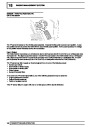
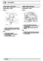
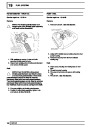
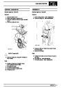
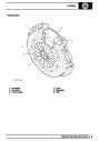
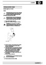
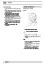
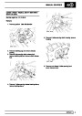
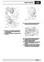
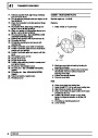
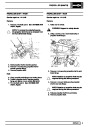
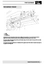
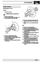
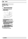
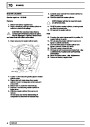
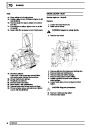
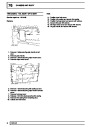
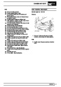
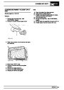
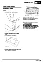
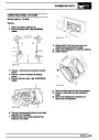
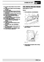
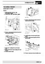
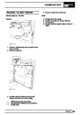
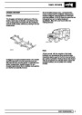
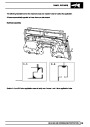
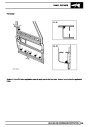
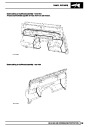
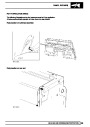
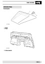
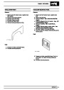
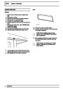
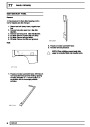
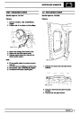
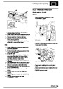
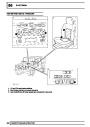
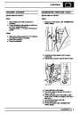
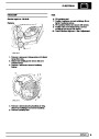
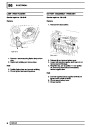
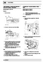
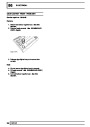
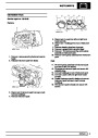
Cylinder head
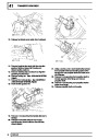
The cylinder head is of aluminium construction. It is not possible to reface the cylinder head if it becomes worn or
damaged. An alloy camshaft carrier is bolted directly to the upper surface of the cylinder head. Two dowels are
included in the cylinder head upper face for correct location of the camshaft carrier.
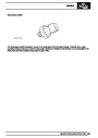
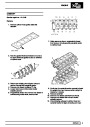
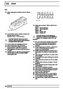
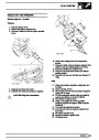
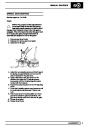
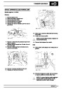
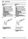
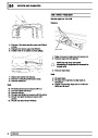
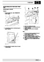
The EU3 cylinder head has a single internal fuel rail for delivering fuel to the injectors and an external fuel pipe for
returning spill fuel back to the fuel connector block. Therefore, pre EU3 and EU3 cylinder heads are not
interchangeable.
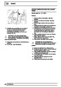
CAUTION: The cylinder head incorporates drillings for the fuel injection system, any
contamination which enters these drillings could cause engine running problems or injector
failure. It is therefore, essential that absolute cleanliness is maintained when carrying out work on
the cylinder head.
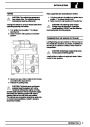
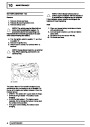
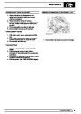
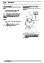
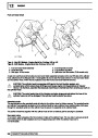
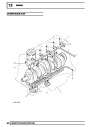
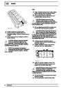
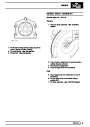
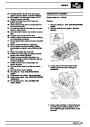
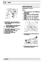
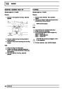
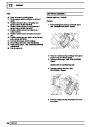
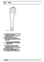
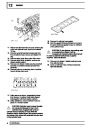
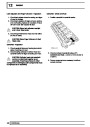
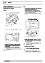
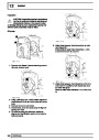
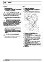
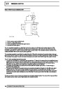
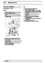
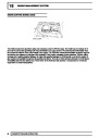
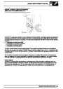
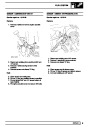
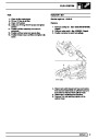
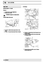
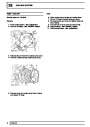
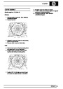
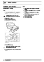
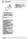
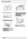
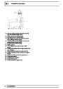
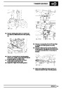
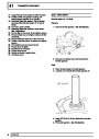
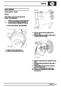
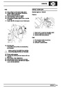
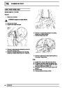
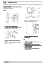
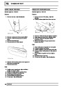
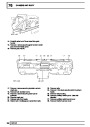
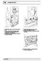
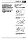
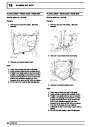
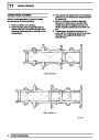
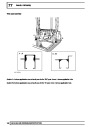
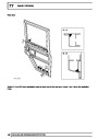
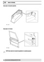
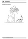
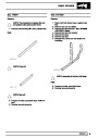
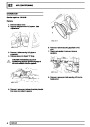
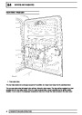
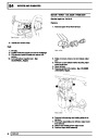
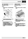
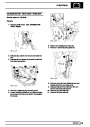
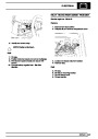
The camshaft carrier and cylinder head assembly is attached to the cylinder block by twelve cylinder head
retaining bolts which pass through the camshaft carrier and the cylinder head to secure the assembly to the
cylinder block.
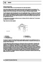
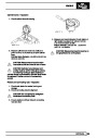
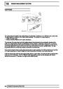
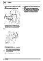
CAUTION: The valve heads, tips of the injectors and glow plugs protrude below the face of the
cylinder head and will be damaged if the cylinder head is stored face down.
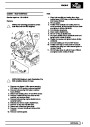
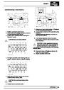
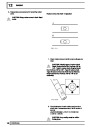
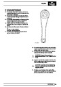
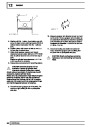
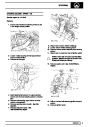
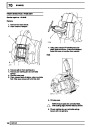
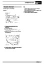
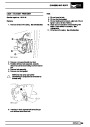
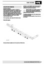
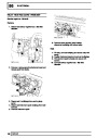
The camshaft is located between the cylinder head and the camshaft carrier, and the bearing journals are line
bored between the two components to form a matched pair.
CAUTION: Always fit plugs to open connections to prevent contamination.
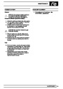
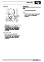
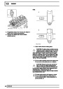
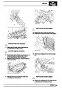
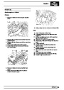
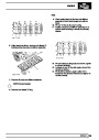
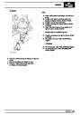
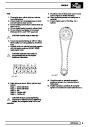
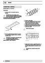
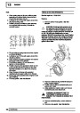
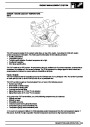
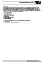
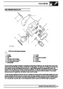
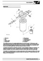
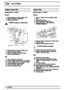
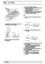
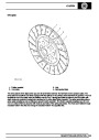
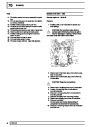
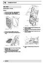
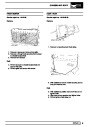
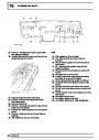
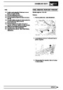
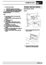
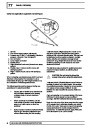
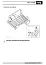
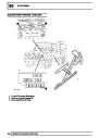
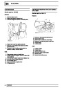
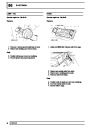
The valve guides and valve seat inserts are sintered components which are an interference fit to the cylinder
head. The cylinder head machining also provide the locations for the electronic unit injectors, glow plugs, hydraulic
lash adjusters, finger followers and low pressure fuel rail.
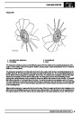
Cooling to the cylinder head is provided by coolant flow through a water jacket machined into the cylinder head.
Drillings through the block provide lubrication channels for pressurised oil supply to cylinder head components
such as the lash adjusters, finger followers, rocker arms and camshaft bearings.
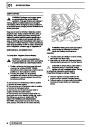
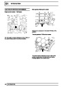
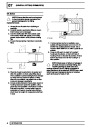
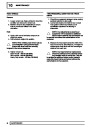
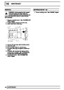
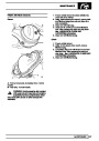
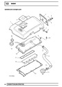
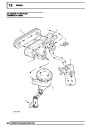
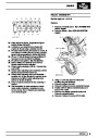
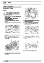
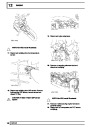
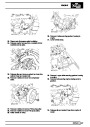
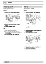
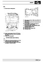
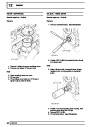
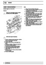
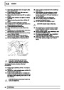
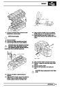
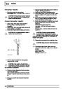
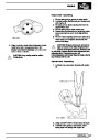
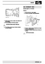
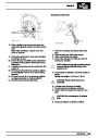
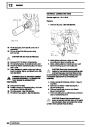
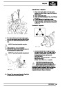
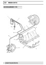
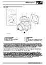
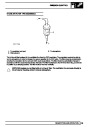
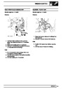
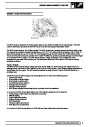
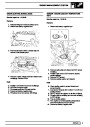
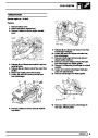
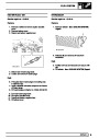
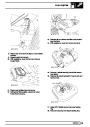
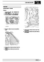
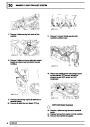
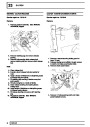
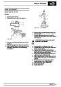
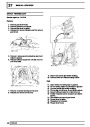
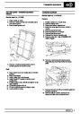
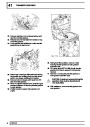
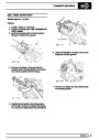
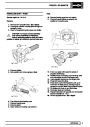
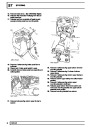
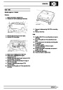
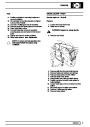
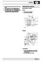
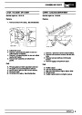
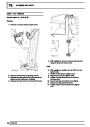
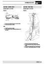
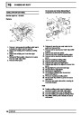
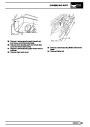
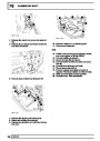
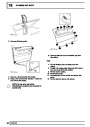
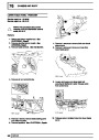
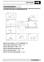
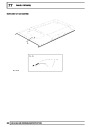
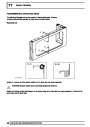
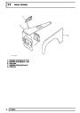
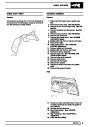
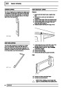
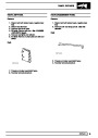
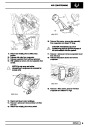
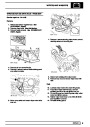
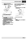
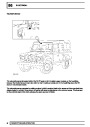
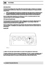
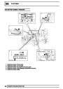
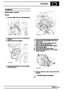
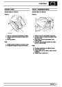
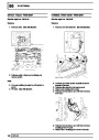
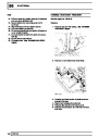
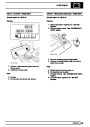
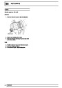
A coolant outlet elbow is fitted to the front LH side of the cylinder head to allow flow of coolant from the cylinder
head back to the radiator. A metal gasket is used to seal the joint between the water outlet elbow and the cylinder
head. A coolant temperature sensor is located in a port in the side of the water outlet elbow for monitoring coolant
temperature.
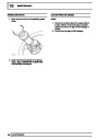
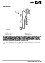
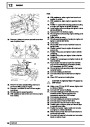
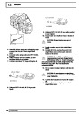
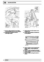
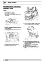
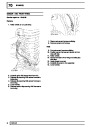
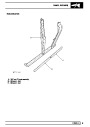
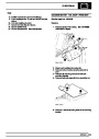
A stub pipe is connected at the front RH side of the cylinder block above the timing cover which connects a pipe to
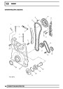
supply oil to the vacuum pump. The timing chain tensioner adjuster is screwed in a thread in the cylinder head at a
location on the front RH side of the engine below the oil feed port for the vacuum pump.
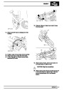
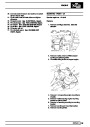
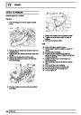
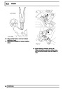
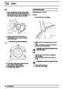
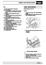
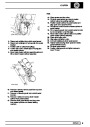
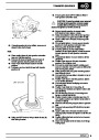
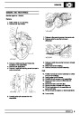
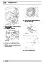
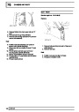
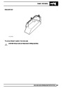
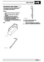
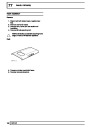
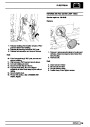
An access hole for the camshaft gear is included at the front of the cylinder head which is sealed with a plastic
plug and rubber ’O’ ring. A press-fit core plug for the chain chest is located on the front face of the cylinder head.
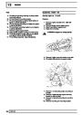
A press-fit core plug for the cylinder head water jacket is located at the rear of the cylinder head and a threaded
brass plug for the water jacket is located on the LH side of the cylinder head beneath the exhaust manifold
assembly.
DESCRIPTION AND OPERATION
25
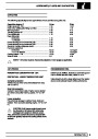
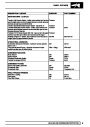
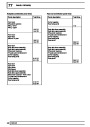
| Categories | Land Rover, Land Rover Defender |
|---|---|
| Tags | Land Rover |
| Model Year | 1999, 2000, 2001, 2002 |
| Download File |
|
| Document Type | Workshop Manual |
| Language | English |
| Product Name | Defender |
| Product Brand | Land Rover |
| Document File Type | |
| Publisher | landrover.com |
| Wikipedia's Page | http://en.wikipedia.org/wiki/Land_Rover |
| Copyright | Attribution Non-commercial |
(0 votes, average: 0 out of 5)