


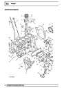

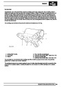


FUEL SYSTEM
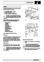
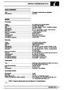
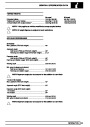
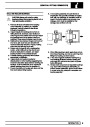
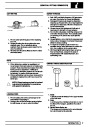
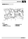
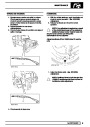
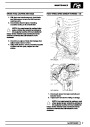
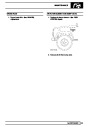
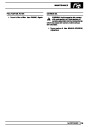
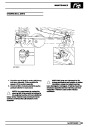
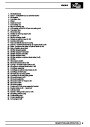
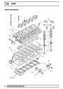
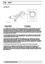
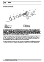
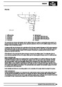
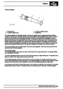
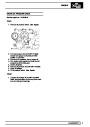
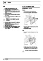
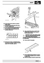
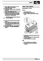
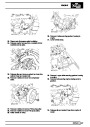
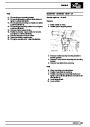
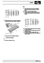
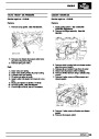
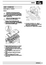
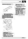
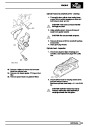
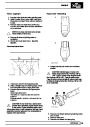
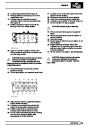
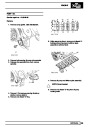
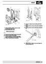
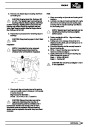
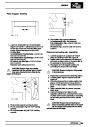
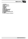
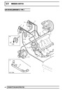
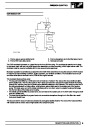
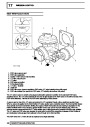
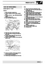
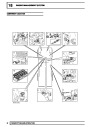
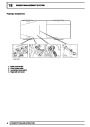
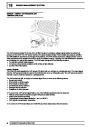
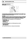
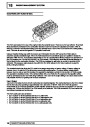
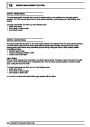
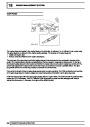
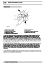
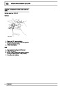
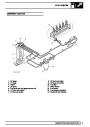
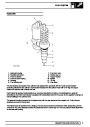
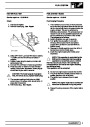
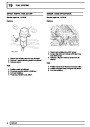
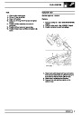
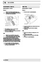
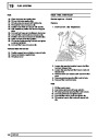
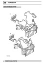
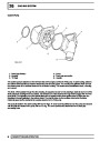
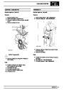
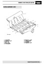
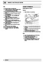
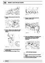
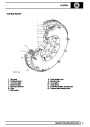
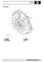
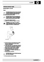
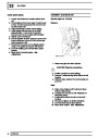
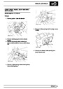
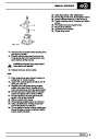
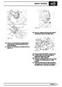
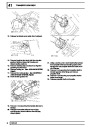
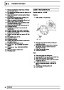
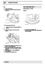
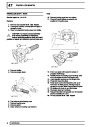
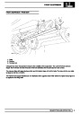
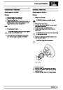
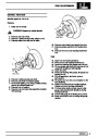
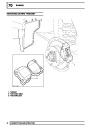
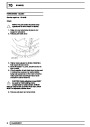
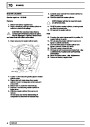
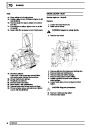
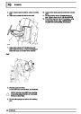
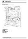
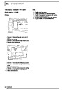
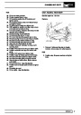
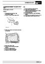
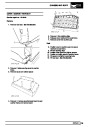
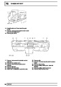
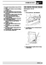
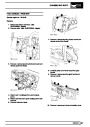
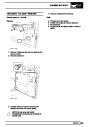
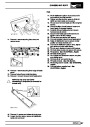
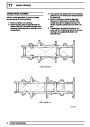
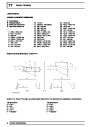
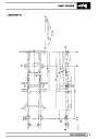
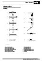
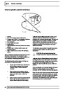
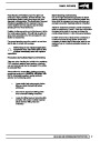
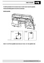
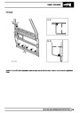
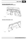
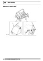
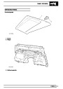
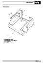
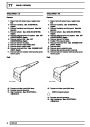
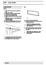
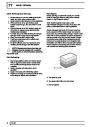
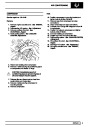
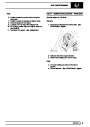
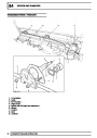
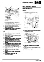
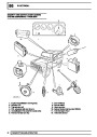
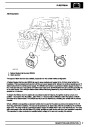
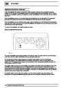
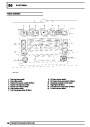
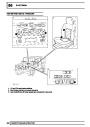
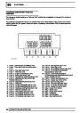
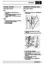
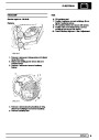
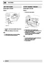
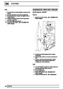
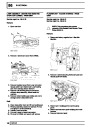
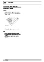
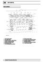
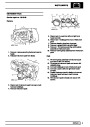
INJECTORS
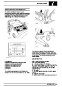
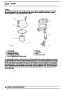
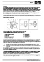
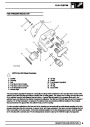
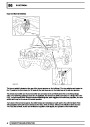
1.
2.
3.
4.
5.
6.
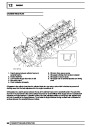
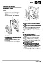
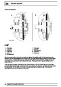
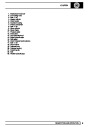
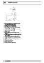
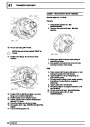
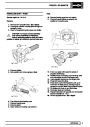
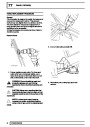
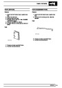
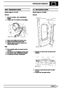
Solenoid housing
7. Fuel return port
Electrical connector
Push rod socket
Push rod return spring
Housing
8. Nozzle cap nut
9. Copper washer
10. Nozzle
11. ’O’ ring
12. Cap screw
Fuel delivery port
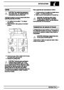
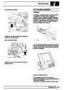
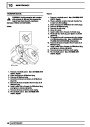
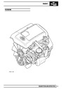
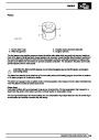
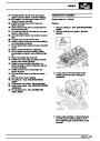
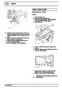
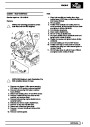
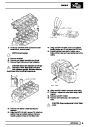
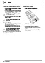
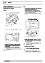
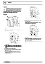
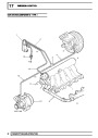
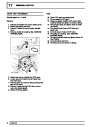
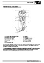
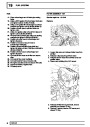
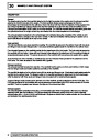
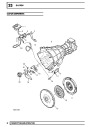
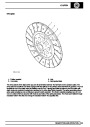
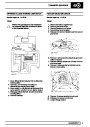
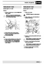
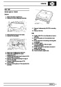
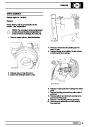
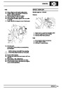
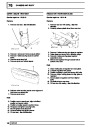
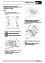
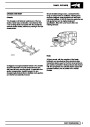
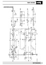
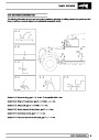
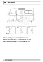
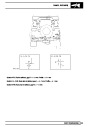
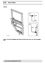
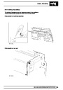
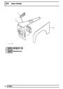
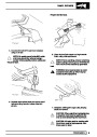
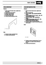
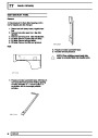
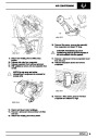
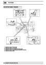
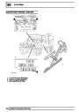
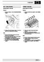
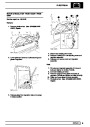
The five injectors are located in the cylinder head adjacent the camshaft, with the nozzle of each injector
protruding directly into the cylinder. Each injector is sealed into the cylinder head with a ’O’ ring and copper
washer and secured with a clamp and bolt.
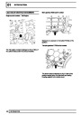
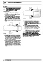
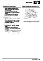
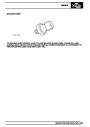
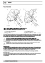
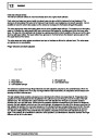
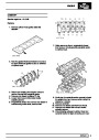
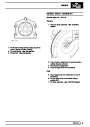
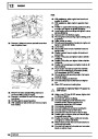
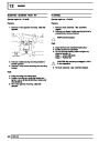
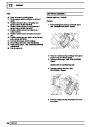
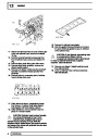
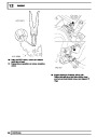
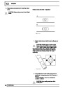
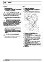
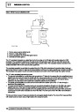
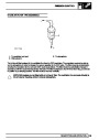
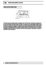
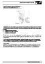
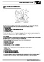
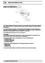
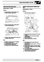
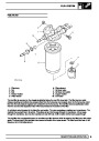
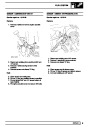
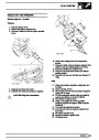
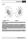
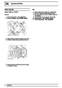
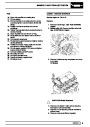
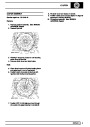
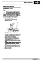
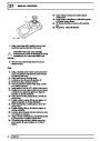
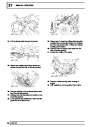
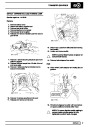
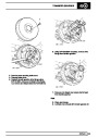
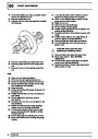
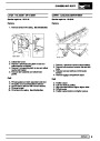
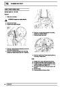
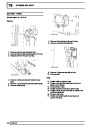
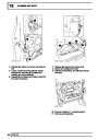
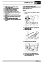
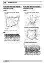
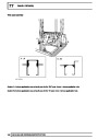
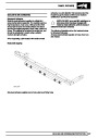
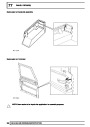
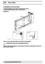
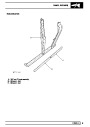
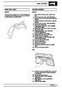
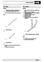
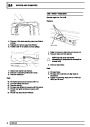
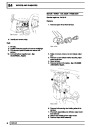
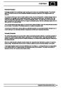
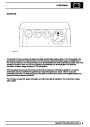
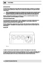
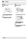
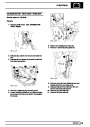
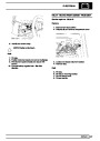
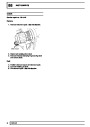
Each injector is operated mechanically by an overhead camshaft and rocker, and electrically by a solenoid
controlled by the ECM. Each injector is supplied with pressurised fuel from the pump via the regulator housing and
internal drillings in the cylinder head.
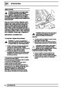
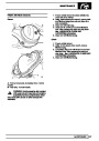
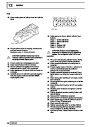
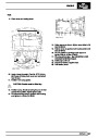
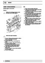
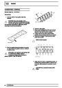
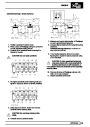
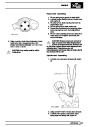
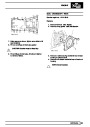
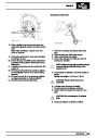
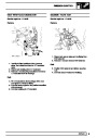
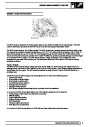
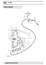
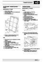
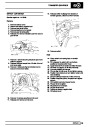
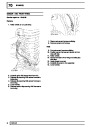
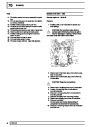
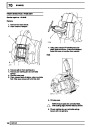
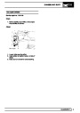
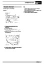
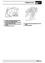
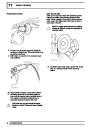
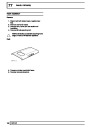
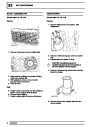
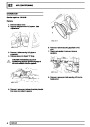
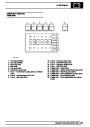
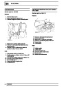
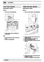
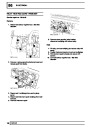
The solenoid housing is secured to the injector body with two cap screws and is a sealed unit. It has a two pin
electrical connector on its top face.
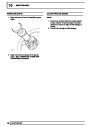
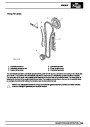
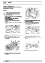
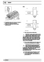
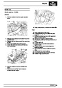
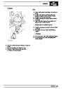
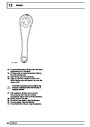
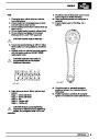
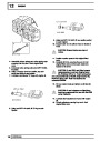
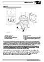
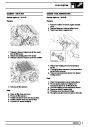
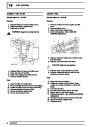
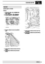
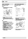
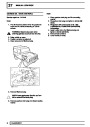
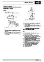
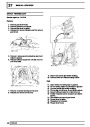
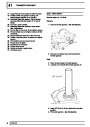
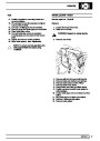
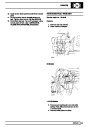
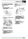
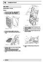
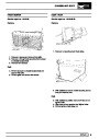
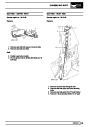
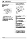
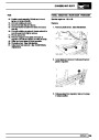
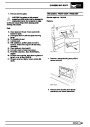
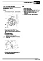
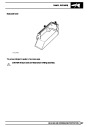
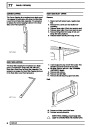
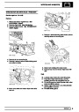
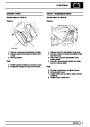
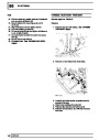
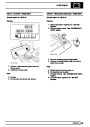
The injector body is machined from a forging. The body has a machined central bore which locates the push rod.
A thread on the outer diameter provides the attachment for the nozzle cap nut. The body also provides attachment
for the solenoid housing.
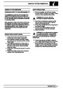
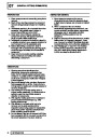
DESCRIPTION AND OPERATION
7
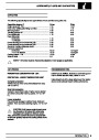
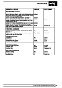
| Categories | Land Rover, Land Rover Defender |
|---|---|
| Tags | Land Rover |
| Model Year | 1999, 2000, 2001, 2002 |
| Download File |
|
| Document Type | Workshop Manual |
| Language | English |
| Product Name | Defender |
| Product Brand | Land Rover |
| Document File Type | |
| Publisher | landrover.com |
| Wikipedia's Page | http://en.wikipedia.org/wiki/Land_Rover |
| Copyright | Attribution Non-commercial |
(0 votes, average: 0 out of 5)