


19
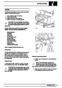
FUEL SYSTEM
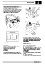
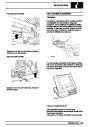
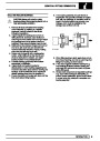
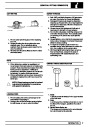
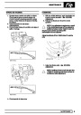
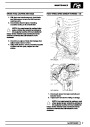
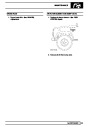
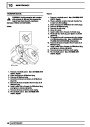
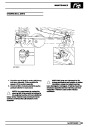
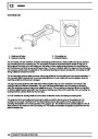
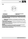
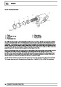
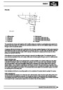
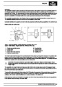
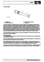
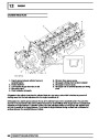
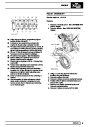
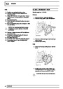
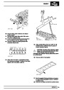
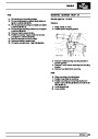
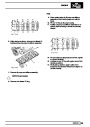
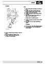
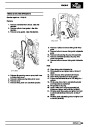
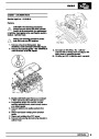
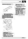
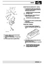
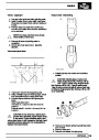
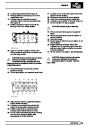
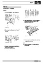
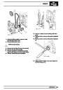
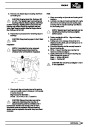
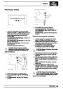
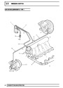
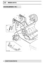
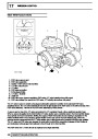
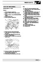
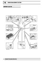
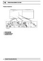
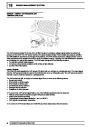
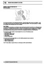
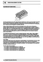
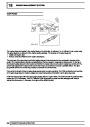
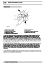
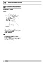
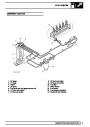
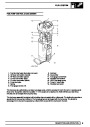
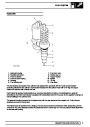
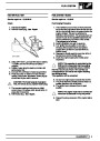
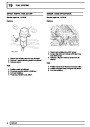
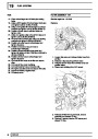
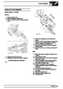
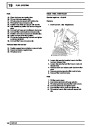
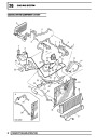
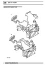
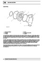
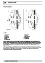
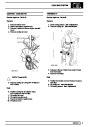
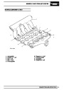
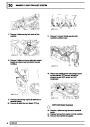
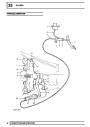
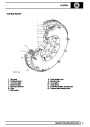
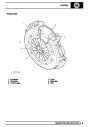
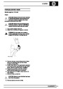
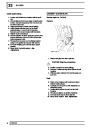
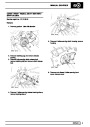
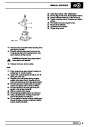
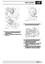
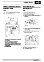
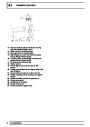
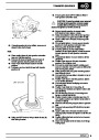
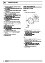
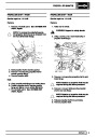
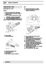
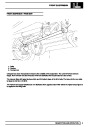
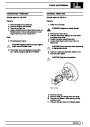
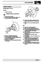
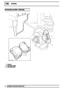
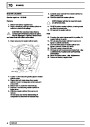
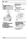
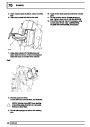
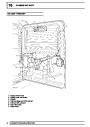
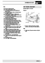
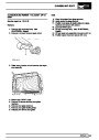
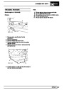
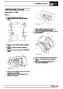
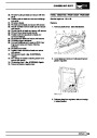
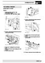
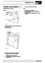
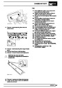
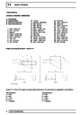
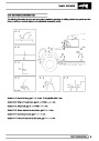
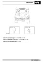
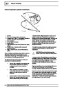
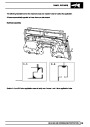
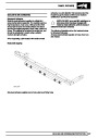
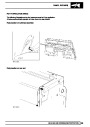
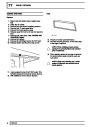
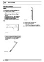
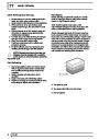
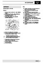
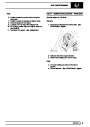
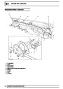
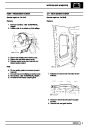
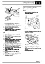
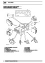
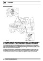
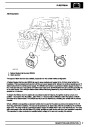
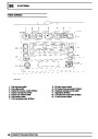
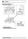
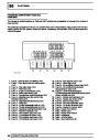
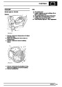
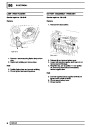
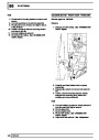
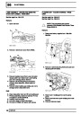
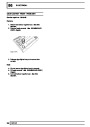
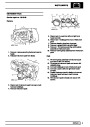
Fuel Pump
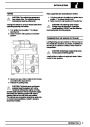
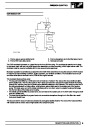
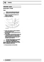
The fuel pump assembly comprises a top cover which locates the electrical connector, and four fuel pipe
couplings. The top cover is attached to a plastic cup shaped housing and retained on three sliding clips. Two coil
springs are located between the cover and the housing and ensure that the fuel pump remains seated positively at
the bottom of the tank when installed.
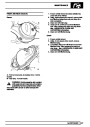
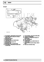
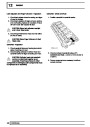
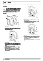
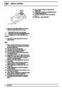
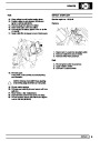
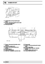
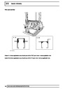
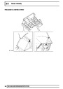
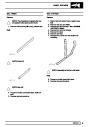
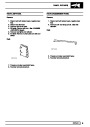
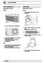
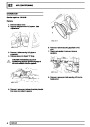
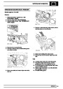
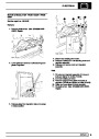
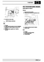
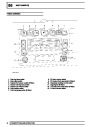
The housing locates the two stage fuel pump and also the fuel gauge sender unit. The lower part of the housing is
the swirl pot which maintains a constant level of fuel at the fuel pick-up. A coarse filter is located in the base of the
housing and prevents the ingress of contaminants into the pump and the fuel system from the fuel being drawn
into the pump. A fine filter is located in the intake to the low pressure stage to protect the pump from
contaminants. Flexible pipes connect the couplings on the top cover to the pump.
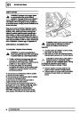
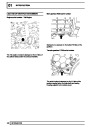
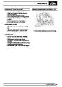
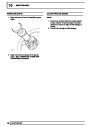
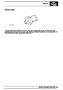
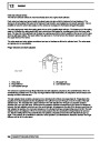
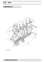
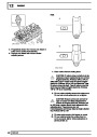
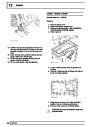
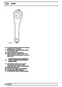
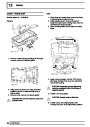
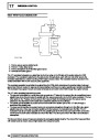
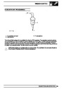
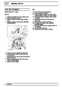
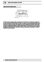
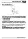
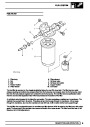
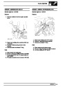
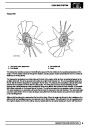
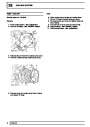
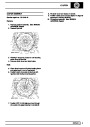
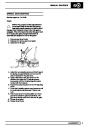
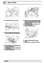
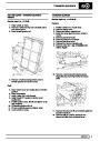
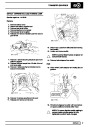
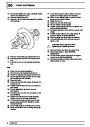
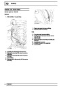
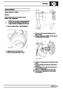
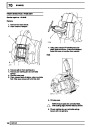
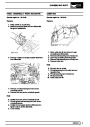
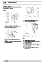
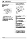
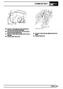
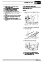
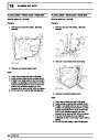
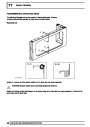
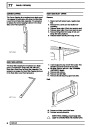
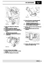
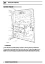
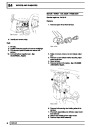
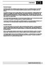
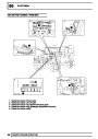
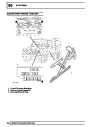
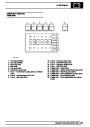
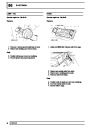
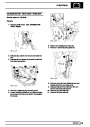
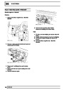
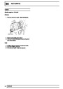
A non-return valve is located in the base of the housing. When the fuel tank is full, fuel pressure keeps the valve
lifted from its seat, allowing fuel to flow into the swirl pot. As the tank level reduces, the fuel pressure in the tank
reduces causing the valve to close. When the valve is closed, fuel is retained in the swirl pot, ensuring that the
swirl pot remains full and maintains a constant supply to the fuel pump.
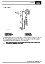
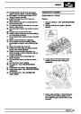
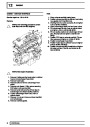
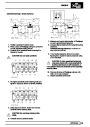
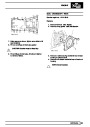
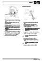
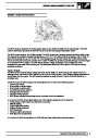
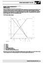
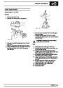
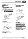
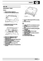
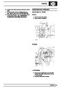
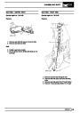
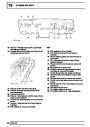
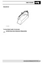
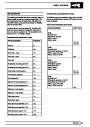
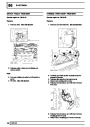
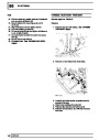
The two stage pump comprises a high and low pressure stage. The low pressure stage draws fuel from the swirl
pot through a filter. The low pressure stage pumps fluid at a pressure of 0.75 bar (10.9 lbf.in) and a flow of 30
litres/hour (8 US Gallons/hour) to the fuel filter. A proportion of the fuel from the low pressure stage also passes,
via a restrictor, through a jet pump which keeps fuel circulating in the swirl pot. The high pressure stage draws the
low pressure fuel from the fuel filter and pressurises it to a pressure of 4.0 bar (58 lbf.in). The pressurised fuel is
then passed from the pump to the injectors at a flow of 180 litres/hour (47.6 US Gallons/hour). A fuel pressure
regulator is located at the rear of the engine and ensures that the delivery pressure remains at 4.0 bar (58 lbf.in)
by controlling the amount of fuel returning to the fuel tank.
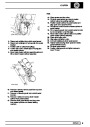
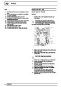
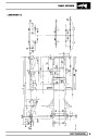
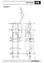
The fuel pump has a maximum current draw of 15 Amps at 12 Volts and is supplied a feed (C0114-1) from the fuel
pump relay (C0730-2) on a white/purple wire.
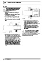
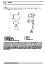
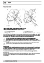
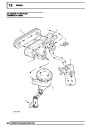
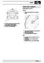
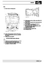
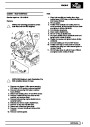
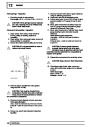
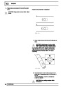
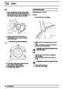
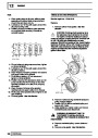
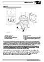
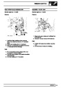
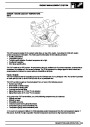
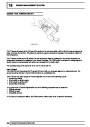
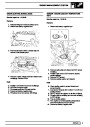
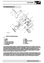
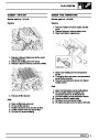
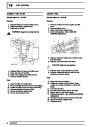
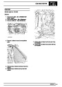
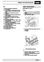
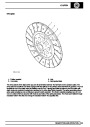
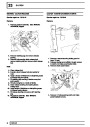
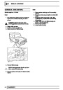
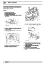
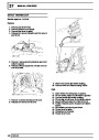
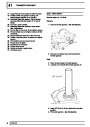
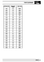
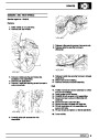
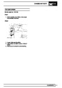
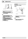
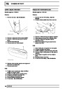
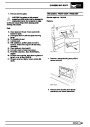
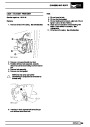
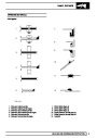
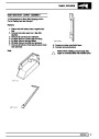
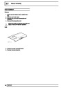
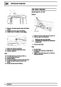
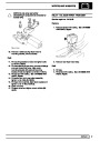
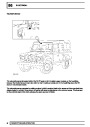
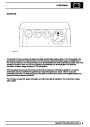
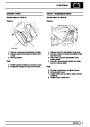
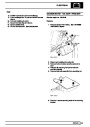
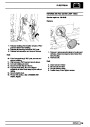
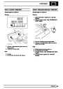
Fuel Gauge Sender
The fuel gauge sender unit comprises a rotary potentiometer operated by a float. The float rises and falls with the
fuel level in the tank and moves the potentiometer accordingly.
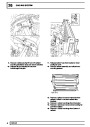
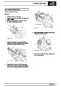
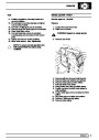
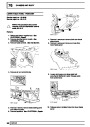
A feed is supplied to the fuel gauge sender (C0114-1) by the fuel pump relay (C0730-2) on a purple/white then
white/purple wire. The sender is earthed (C0114-3) on a slate/black wire via header 287. The output voltage
(C0114-2) from the sender to the instrument pack (C1061-3) varies in relation to the fuel level. This output voltage
is connected to the fuel gauge C1054-2). The fuel gauge receives a battery voltage input (C1054-3) on a
white/green wire. This is compared with the output voltage from the potentiometer. The difference between the two
voltages determines the deflection of the fuel gauge pointer.
4
DESCRIPTION AND OPERATION
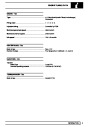
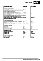
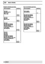
| Categories | Land Rover, Land Rover Defender |
|---|---|
| Tags | Land Rover |
| Model Year | 1999, 2000, 2001, 2002 |
| Download File |
|
| Document Type | Workshop Manual |
| Language | English |
| Product Name | Defender |
| Product Brand | Land Rover |
| Document File Type | |
| Publisher | landrover.com |
| Wikipedia's Page | http://en.wikipedia.org/wiki/Land_Rover |
| Copyright | Attribution Non-commercial |
(0 votes, average: 0 out of 5)