


18
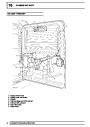
ENGINE MANAGEMENT SYSTEM
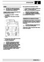
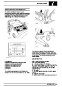
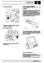
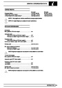
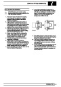
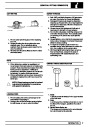
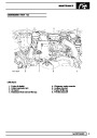
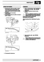
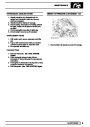
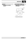
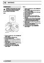
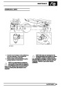
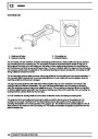
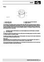
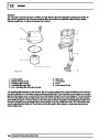
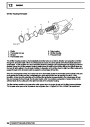
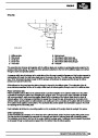
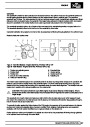
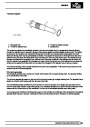
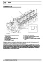
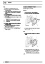
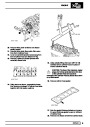
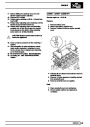
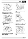
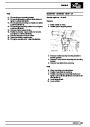
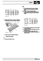
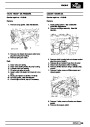
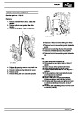
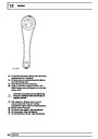
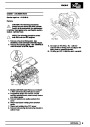
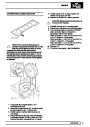
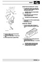
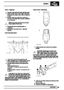
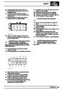
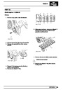
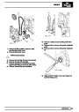
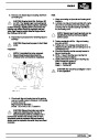
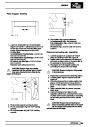
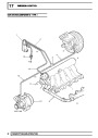
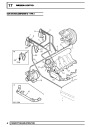
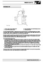
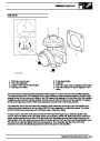
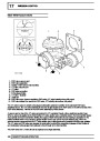
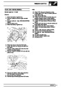
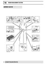
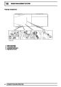
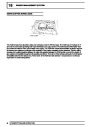
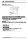
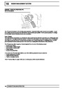
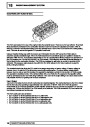
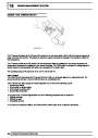
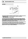
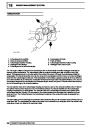
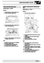
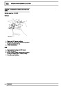
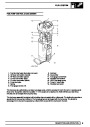
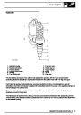
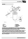
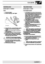
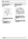
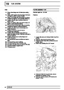
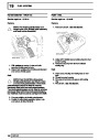
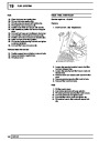
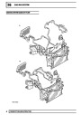
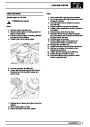
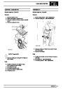
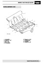
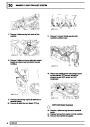
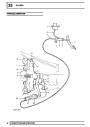
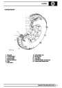
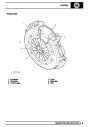
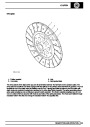
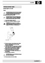
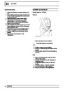
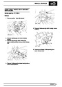
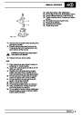
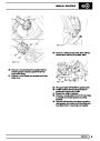
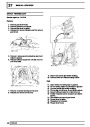
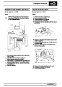
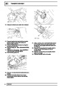
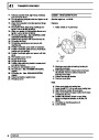
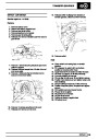
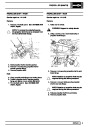
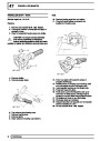
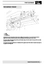
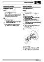
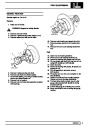
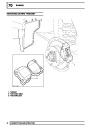
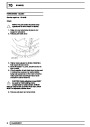
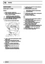
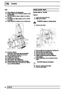
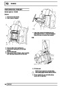
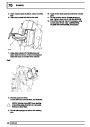
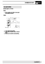
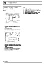
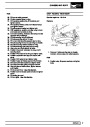
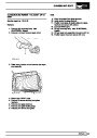
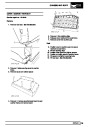
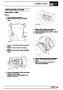
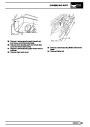
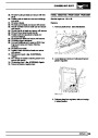
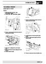
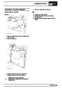
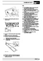
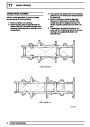
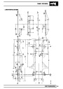
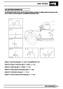
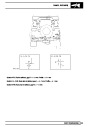
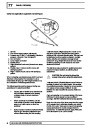
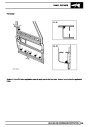
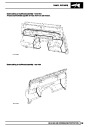
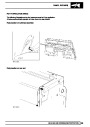
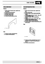
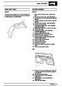
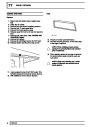
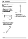
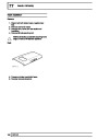
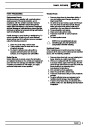
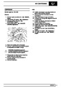
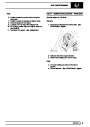
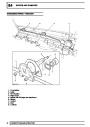
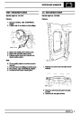
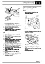
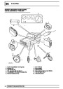
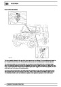
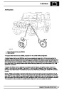
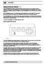
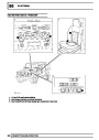
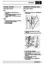
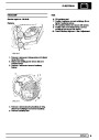
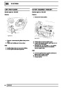
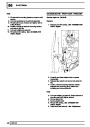
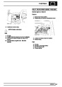
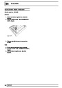
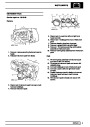
SENSOR - THROTTLE POSITION (TP)
UP TO VIN 607224
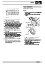
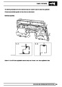
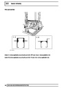
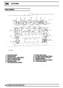
The TP sensor is located on the throttle pedal assembly. It detects throttle pedal movement and position. It uses
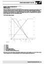
two position sensors to provide the ECM with the exact throttle pedal position. As the pedal operates, the voltage
of one position sensor increases as the other decreases.
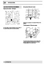
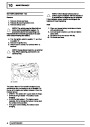
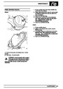
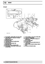
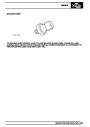
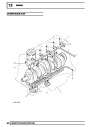
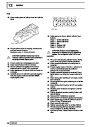
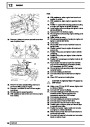
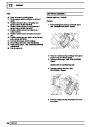
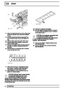
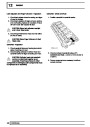
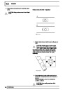
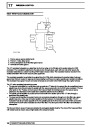
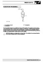
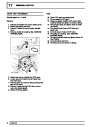
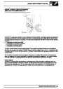
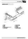
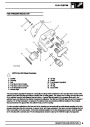
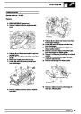
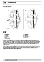
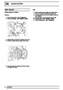
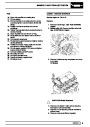
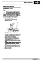
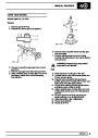
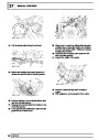
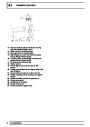
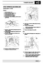
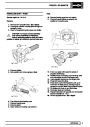
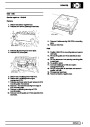
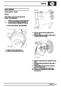
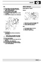
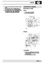
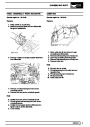
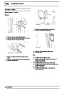
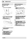
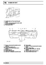
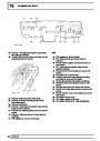
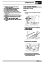
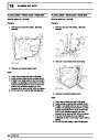
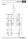
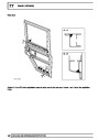
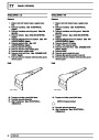
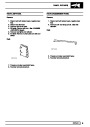
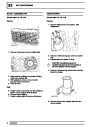
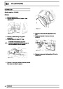
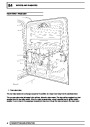
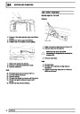
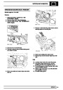
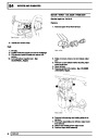
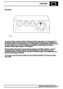
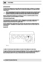
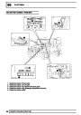
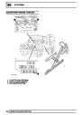
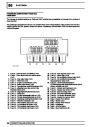
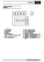
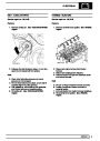
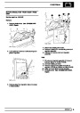
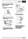
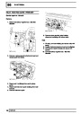
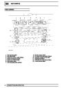
Input / Output
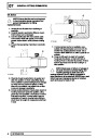
The ECM (C0658-14) provides a 5 volt reference feed to both sensors (C0787-B & C0787-J) on white/purple wires
via header 291. The signal output from sensor 1 (C0787-F) is connected to the ECM (C0658-12) by a white/green
wire. Signal output from sensor 2 (C787-K) is connected to the ECM (C0658-36) by a white/slate wire. An earth
path is provided for both sensors (C0787-B & C0787-G) on black/yellow wires via the ECM (C0658-26)
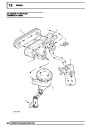
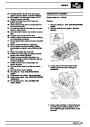
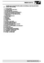
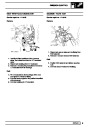
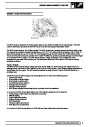
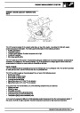
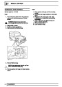
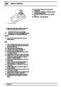
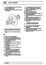
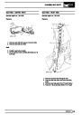
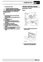
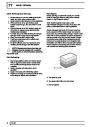
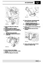
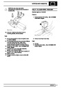
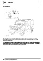
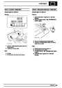
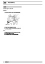
The TP sensor can fail or supply an incorrect signal if one or more of the following occurs:
•
•
•
•
•
Sensor open circuit.
Short circuit to vehicle supply.
Short circuit to vehicle earth.
Water ingress.
Sensor incorrectly fitted.
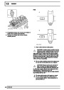
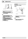
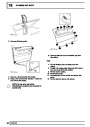
In the event of a TP sensor signal failure, any of the following symptoms may be observed:
•
•
•
Engine performance concern.
Delayed throttle response.
Failure of emission control.
If the TP sensor fails, the engine will only run at idle speed until the fault is eliminated.
14
DESCRIPTION AND OPERATION
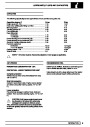
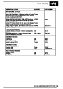
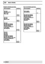
| Categories | Land Rover, Land Rover Defender |
|---|---|
| Tags | Land Rover |
| Model Year | 1999, 2000, 2001, 2002 |
| Download File |
|
| Document Type | Workshop Manual |
| Language | English |
| Product Name | Defender |
| Product Brand | Land Rover |
| Document File Type | |
| Publisher | landrover.com |
| Wikipedia's Page | http://en.wikipedia.org/wiki/Land_Rover |
| Copyright | Attribution Non-commercial |
(0 votes, average: 0 out of 5)