


ENGINE
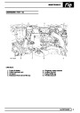
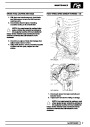
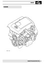
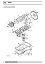
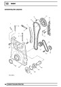
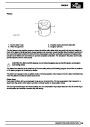
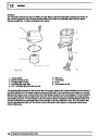
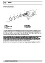
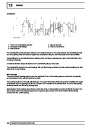
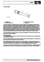
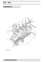
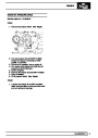
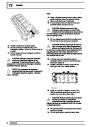
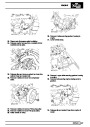
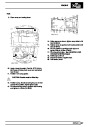
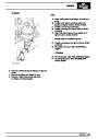
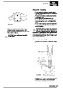
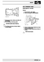
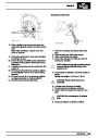
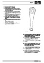
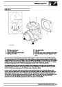
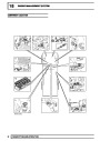
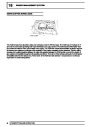
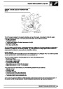
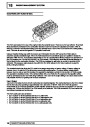
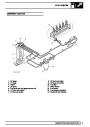
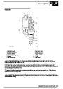
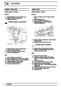
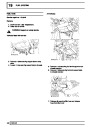
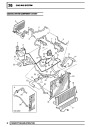
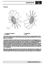
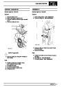
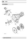
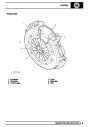
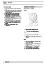
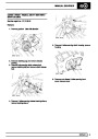
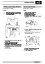
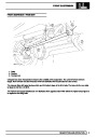
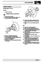
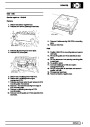
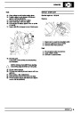
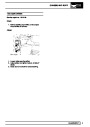
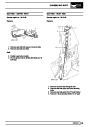
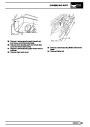
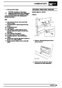
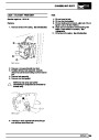
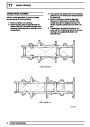
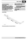
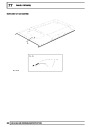
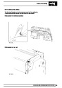
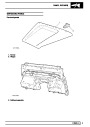
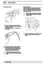
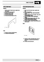
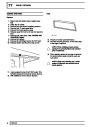
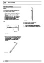
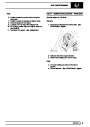
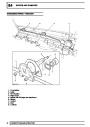
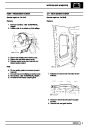
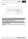
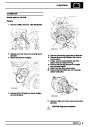
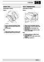
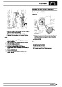
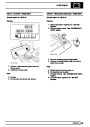
Camshaft
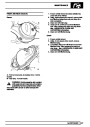
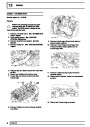
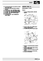
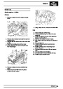
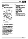
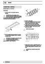
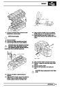
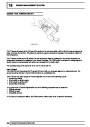
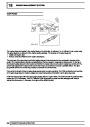
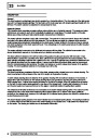
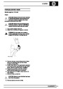
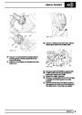
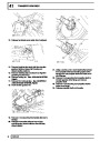
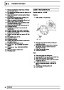
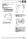
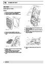
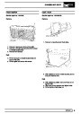
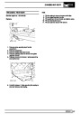
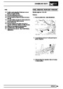
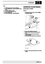
The camshaft is machined from cast steel and is located between the cylinder head and the camshaft carrier and
the six bearing journals are line bored between the two components to form a matched pair. The machined
camshaft has 15 lobes. Ten lobes operate the inlet and exhaust valves through hydraulic lash adjusters and finger
followers which are located below the camshaft. Five larger lobes activate the injector rockers which are located
above the camshaft on the rocker shaft and are used to generate fuel pressure in the EUI injectors.
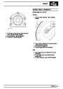
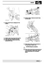
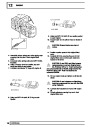
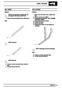
The camshaft sprocket is driven via a Duplex chain connected to the crankshaft sprocket at a speed ratio of 2:1.
The camshaft sprocket is fixed to the front end of the camshaft by three bolts.
Camshaft lubrication is by splash and channel fed via pressurised oil flowing through galleries in the cylinder head.
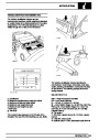
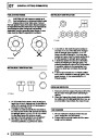
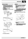
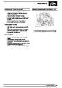
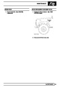
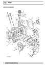
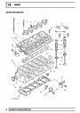
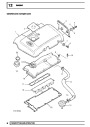
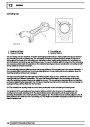
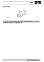
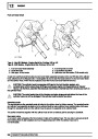
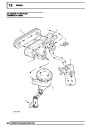
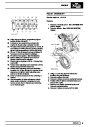
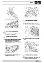
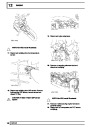
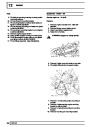
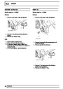
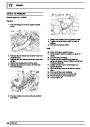
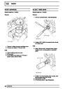
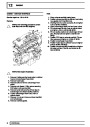
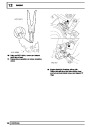
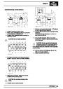
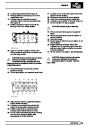
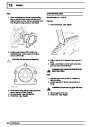
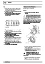
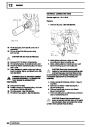
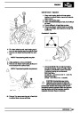
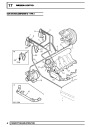
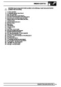
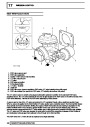
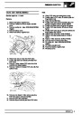
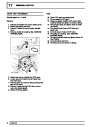
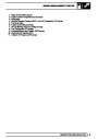
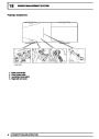
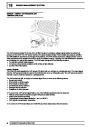
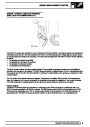
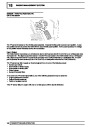
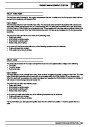
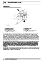
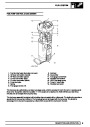
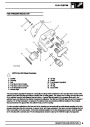
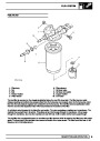
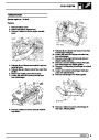
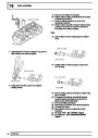
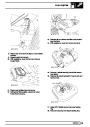
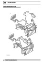
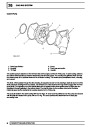
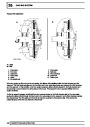
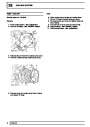
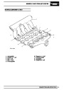
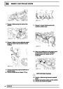
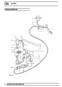
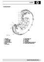
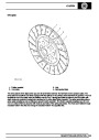
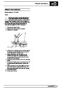
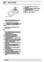
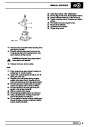
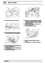
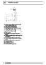
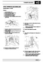
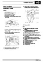
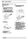
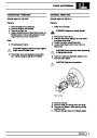
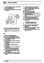
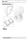
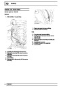
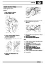
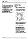
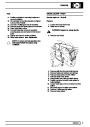
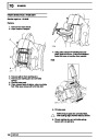
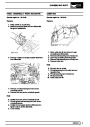
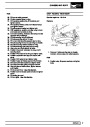
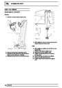
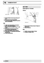
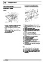
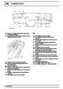
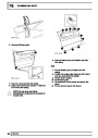
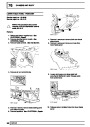
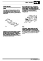
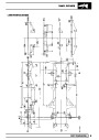
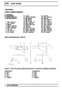
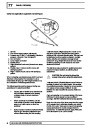
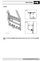
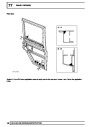
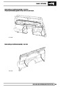
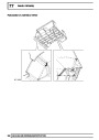
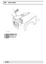
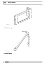
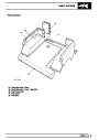
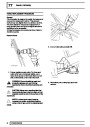
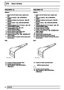
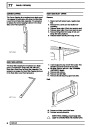
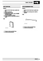
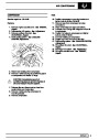
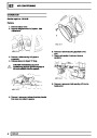
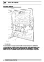
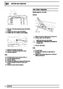
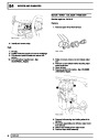
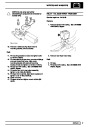
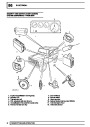
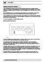
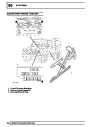
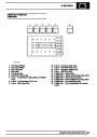
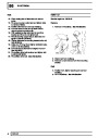
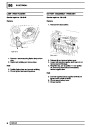
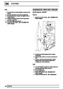
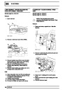
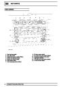
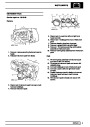
Rocker shaft and rocker arms
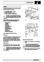
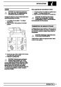
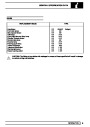
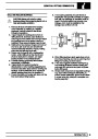
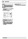
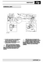
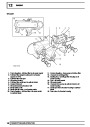
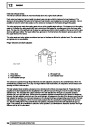
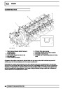
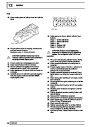
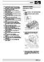
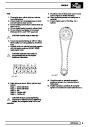
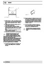
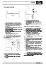
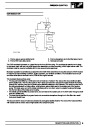
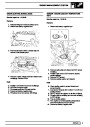
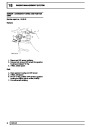
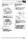
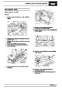
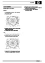
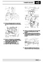
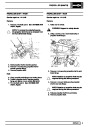
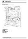
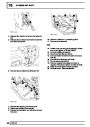
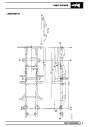
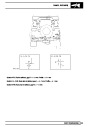
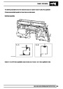
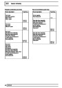
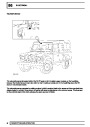
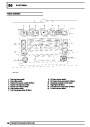
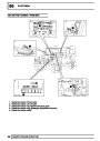
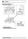
Type A - Non EU3 Models - Engine Serial No. Prefixes 10P to 14P
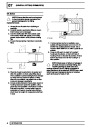
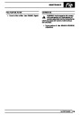
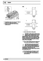
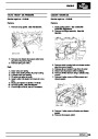
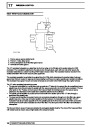
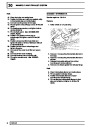
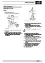
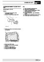
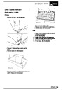
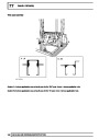
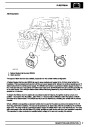
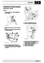
Type B - EU3 Models - Engine Serial No. Prefixes 15P to 19p
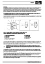
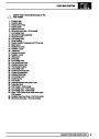
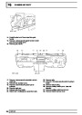
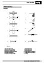
1.
2.
3.
4.
5.
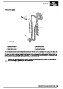
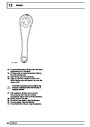
Rocker arm adjusting screw
Rocker shaft
Rocker arm
EUI pin and roller assembly
Roller pin retention slug
6. Camshaft lobe
7. Injector spring
8. Injector push-rod
9. Adjusting nut
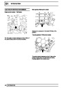
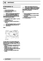
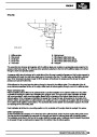
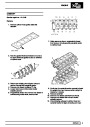
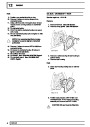
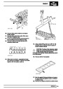
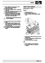
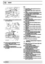
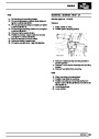
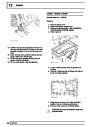
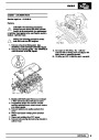
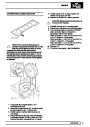
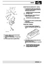
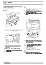
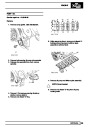
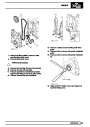
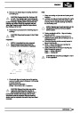
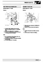
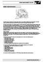
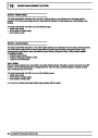
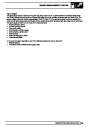
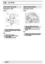
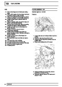
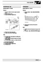
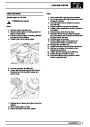
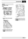
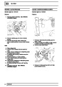
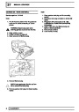
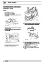
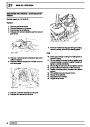
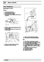
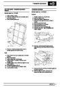
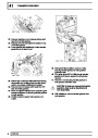
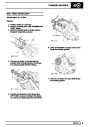
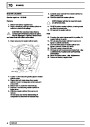
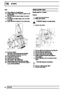
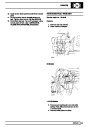
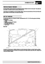
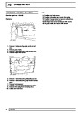
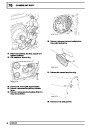
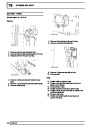
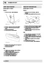
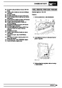
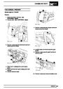
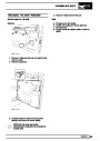
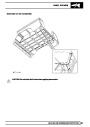
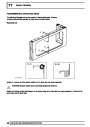
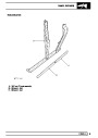
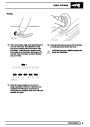
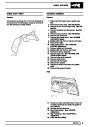
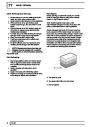
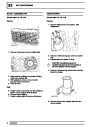
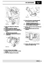
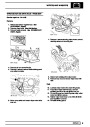
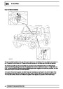
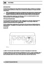
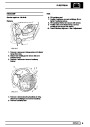
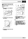
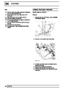
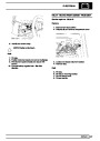
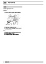
The hollow rocker shaft is located in the camshaft carrier in six fixed mountings which sit above the camshaft. Six
bolts are used to lock the rocker shaft to the camshaft carrier. The front rocker shaft bearing has a ring dowel
located at the front rocker shaft mounting of the camshaft carrier for rocker shaft alignment. Two circlips hold each
rocker arm in position at the relevant positions on the rocker shaft.
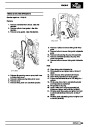
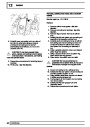
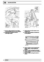
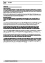
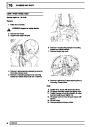
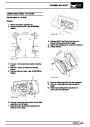
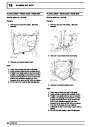
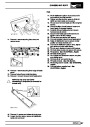
CAUTION: The rocker shaft from a pre EU3 engine must not be fitted to an EU3 engine. This is
because the stroke of the EU3 injector has increased which requires the rocker to articulate over a
larger angle.
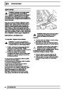
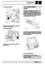
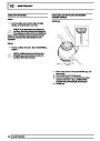
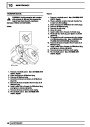
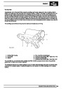
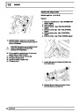
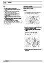
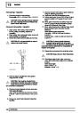
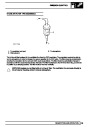
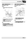
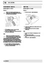
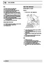
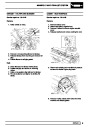
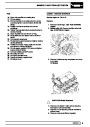
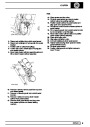
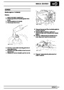
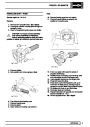
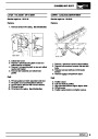
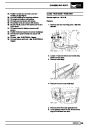
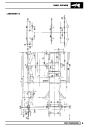
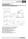
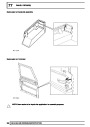
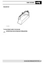
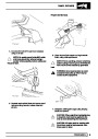
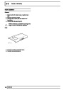
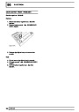
The camshaft end of each rocker arm features a roller which is free to rotate about a pin which passes through
two webs in the rocker arm, the roller pins are held in place by an interference fit retention slug passing through a
hole in the front web of each rocker arm.
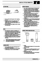
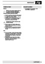
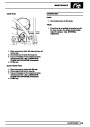
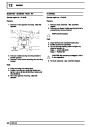
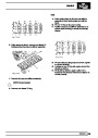
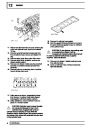
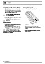
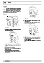
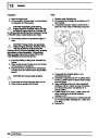
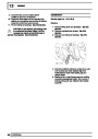
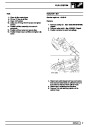
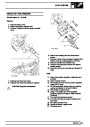
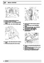
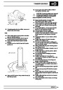
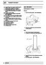
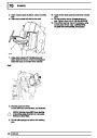
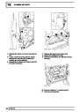
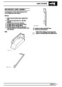
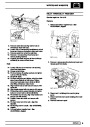
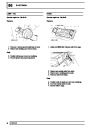
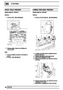
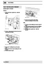
To correctly function against the higher loads of the EU3 engine the geometry of the contact between the injector
pushrod and rocker arm adjusting screw has been modified. Both designs of adjusting screw are separately
available, with the EU3 version identified by an engraved dimple on the slotted end.
Rocker shaft and rocker arm lubrication is by splash and channel fed via pressurised oil flowing through galleries
in the cylinder head and through the rocker shaft.
DESCRIPTION AND OPERATION
27
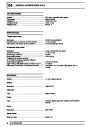
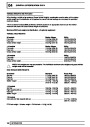
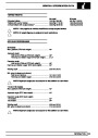
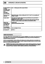
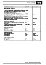
| Categories | Land Rover, Land Rover Defender |
|---|---|
| Tags | Land Rover |
| Model Year | 1999, 2000, 2001, 2002 |
| Download File |
|
| Document Type | Workshop Manual |
| Language | English |
| Product Name | Defender |
| Product Brand | Land Rover |
| Document File Type | |
| Publisher | landrover.com |
| Wikipedia's Page | http://en.wikipedia.org/wiki/Land_Rover |
| Copyright | Attribution Non-commercial |
(0 votes, average: 0 out of 5)