


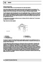


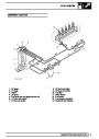


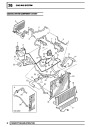
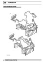


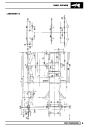


ENGINE MANAGEMENT SYSTEM
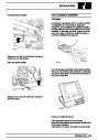
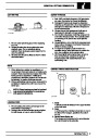
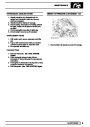
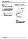
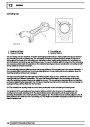
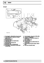
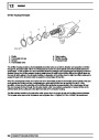
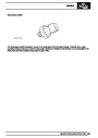
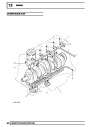
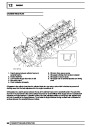
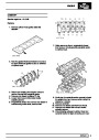
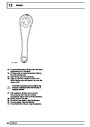
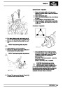
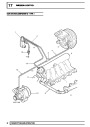
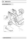
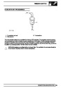
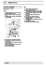
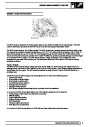
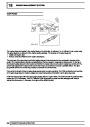
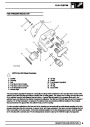
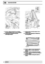
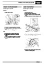
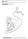
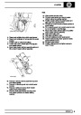
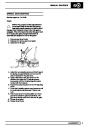
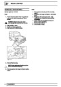
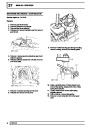
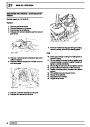
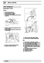
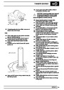
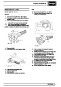
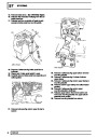
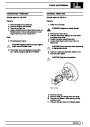
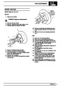
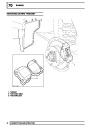
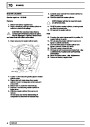
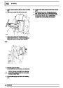
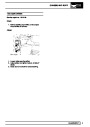
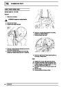
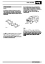
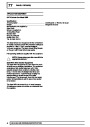
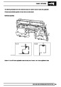
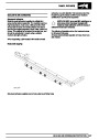
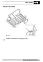
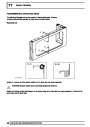
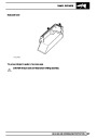
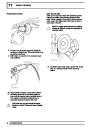
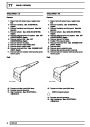
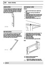
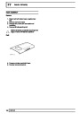
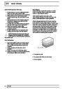
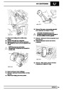
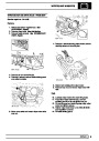
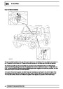
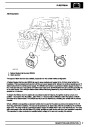
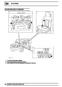
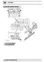
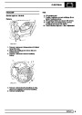
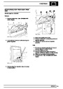
SENSOR - THROTTLE POSITION (TP)
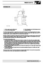
FROM VIN 607225
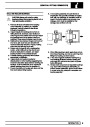
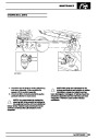
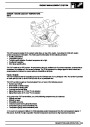
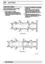
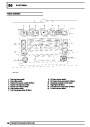
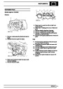
Defender vehicles from VIN 607225 use three track thick film potentiometers. No idle speed sender switch is used
on this type of sensor because the ECM can compare the two or three sets of signals to implement idle speed
control and over-run fuel shut-off. The two potentiometers are known as track 1 and 2 potentiometers. The track 3
potentiometer on later models is used to improve the resolution of the pedal. The ECM provides a 5V supply and
receives a signal from each of the potentiometer tracks.
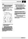
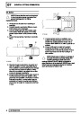
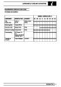
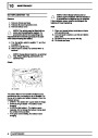
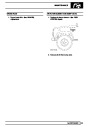
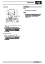
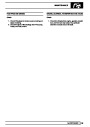
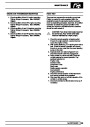
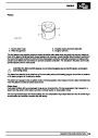
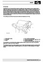
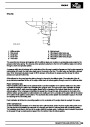
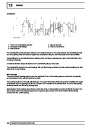
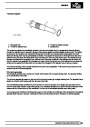
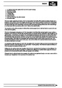
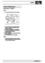
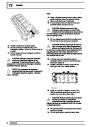
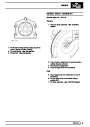
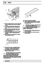
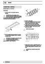
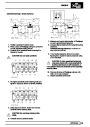
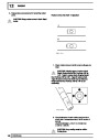
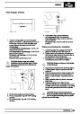
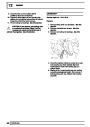
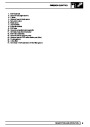
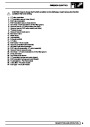
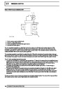
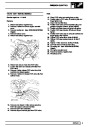
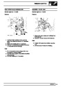
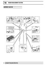
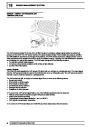
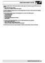
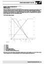
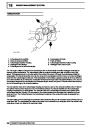
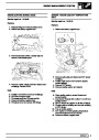
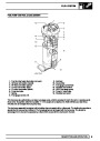
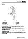
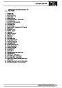
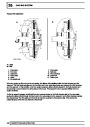
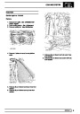
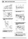
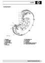
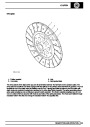
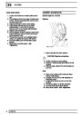
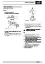
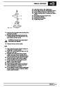
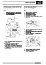
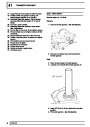
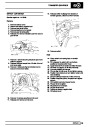
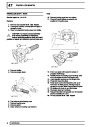
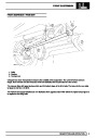
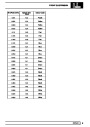
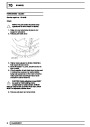
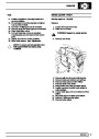
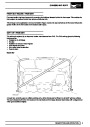
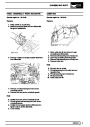
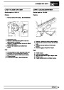
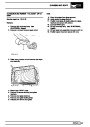
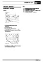
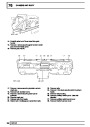
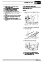
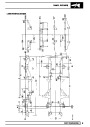
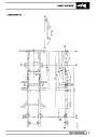
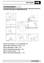
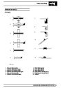
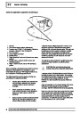
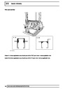
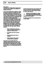
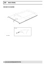
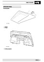
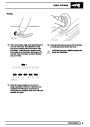
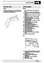
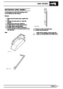
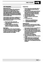
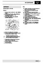
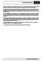
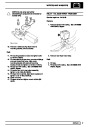
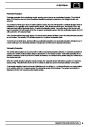
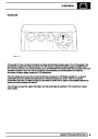
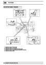
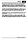
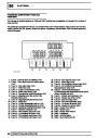
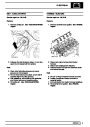
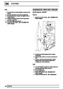
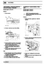
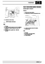
Td5 TP Sensor Signal Output
•
•
•
•
•
•
•
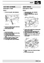
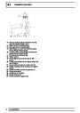
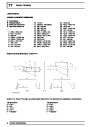
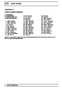
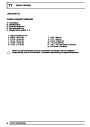
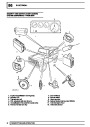
A = Track 1
B = Track 2
C = Track 3
D = Voltage
E = Pedal Angle (Degrees)
F = Not applicable for Defender
G = Wide open throttle stop tolerance band
With reference to the above graph, at idle (throttle released), track 2 returns a signal of 4.2V to the ECM and track
1 returns a signal of 0.8V. The ECM calculates the sum of these two figures which totals 5.0V.
DESCRIPTION AND OPERATION
15
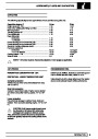
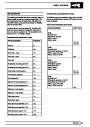
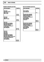
| Categories | Land Rover, Land Rover Defender |
|---|---|
| Tags | Land Rover |
| Model Year | 1999, 2000, 2001, 2002 |
| Download File |
|
| Document Type | Workshop Manual |
| Language | English |
| Product Name | Defender |
| Product Brand | Land Rover |
| Document File Type | |
| Publisher | landrover.com |
| Wikipedia's Page | http://en.wikipedia.org/wiki/Land_Rover |
| Copyright | Attribution Non-commercial |
(0 votes, average: 0 out of 5)