


12
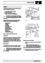
ENGINE
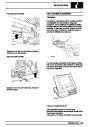
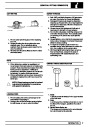
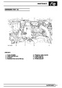
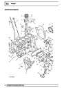
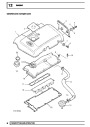
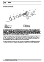
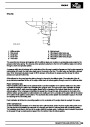
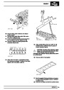
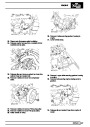
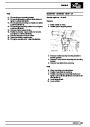
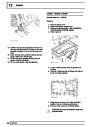
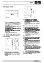
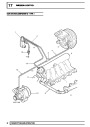
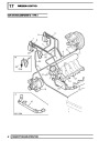
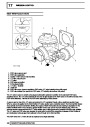
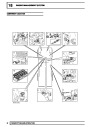
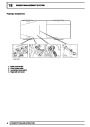
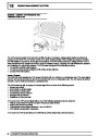
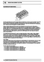
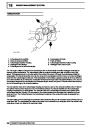
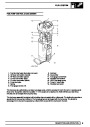
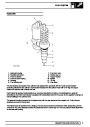
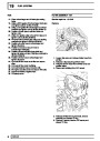
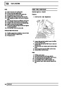
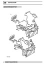
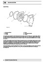
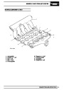
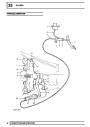
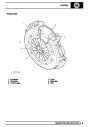
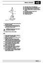
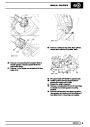
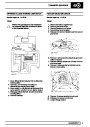
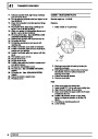
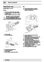
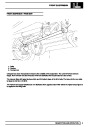
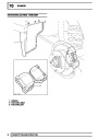
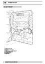
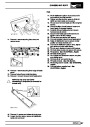
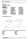
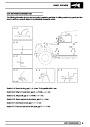
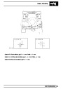
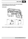
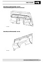
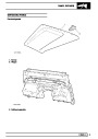
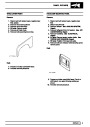
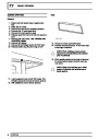
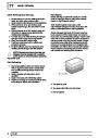
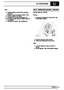
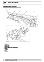
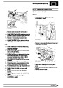
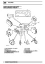
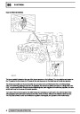
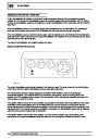
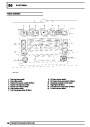
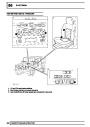
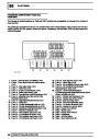
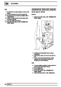
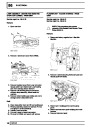
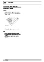
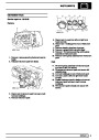
CAMSHAFT COVER COMPONENTS
The camshaft cover cover components are described below:
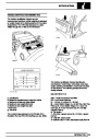
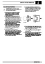
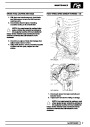
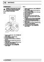
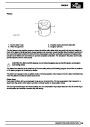
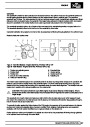
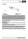
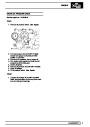
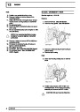
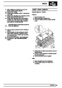
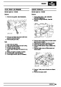
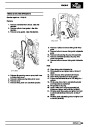
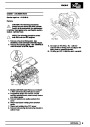
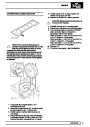
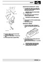
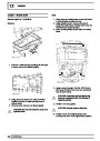
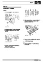
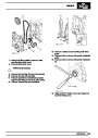
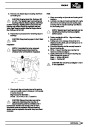
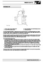
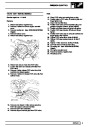
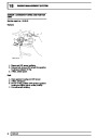
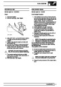
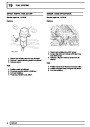
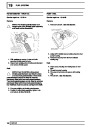
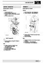
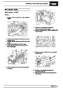
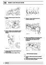
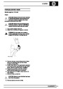
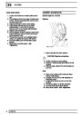
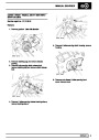
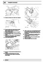
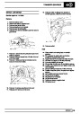
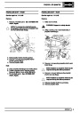
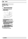
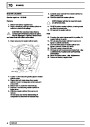
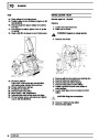
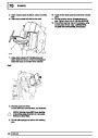
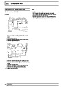
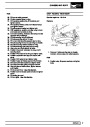
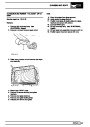
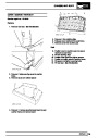
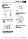
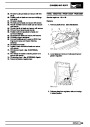
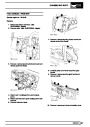
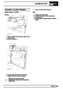
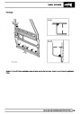
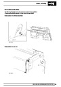
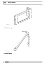
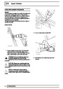
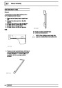
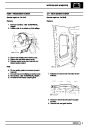
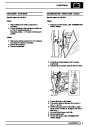
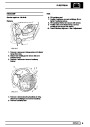
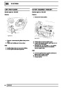
Camshaft cover
The camshaft cover is cast from aluminium alloy and is fixed to the camshaft carrier / cylinder head assembly by
thirteen bolts. The cover has spacers and sealing washers inserted into each of the thirteen bolt holes.
A breather hose is connected to a port at the top of the camshaft cover by means of a hose clip which vents
crankcase gases back to the air intake via a breather valve in the air intake tract, located forward of the
turbocharger in the flexible air intake duct.
A rubber seal is fitted between the camshaft cover and camshaft carrier.
An oil filler aperture is included in the top of the camshaft cover, which is sealed with a plastic cap with integral
rubber seal.
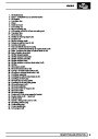
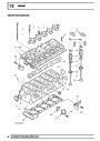
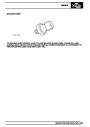
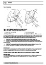
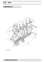
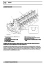
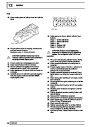
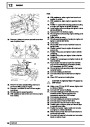
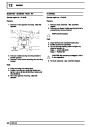
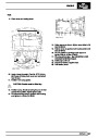
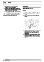
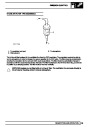
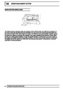
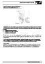
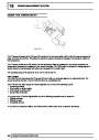
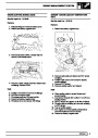
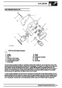
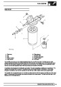
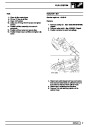
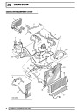
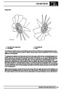
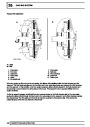
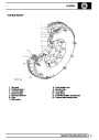
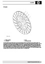
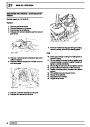
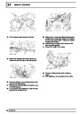
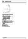
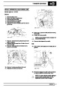
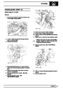
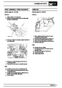
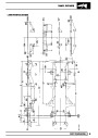
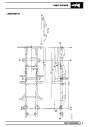
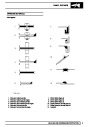
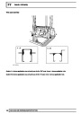
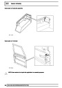
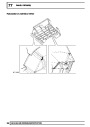
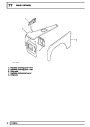
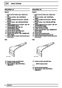
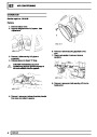
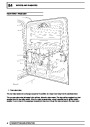
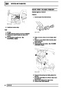
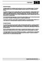
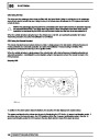
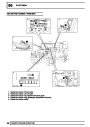
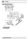
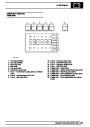
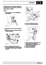
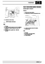
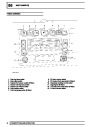
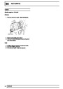
CAMSHAFT TIMING CHAIN COMPONENTS
The timing chain cover and timing chain components are described below:
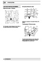
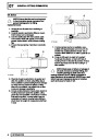
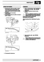
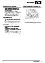
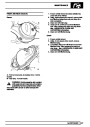
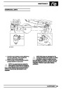
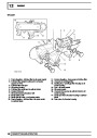
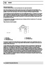
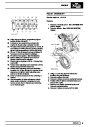
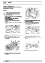
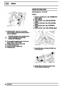
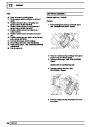
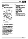
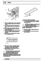
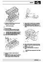
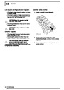
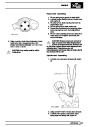
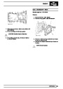
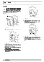
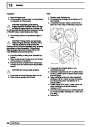
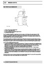
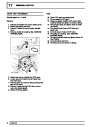
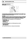
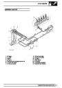
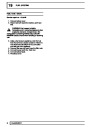
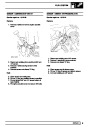
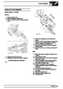
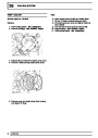
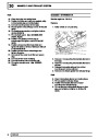
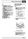
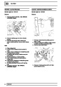
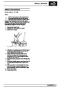
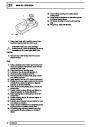
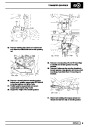
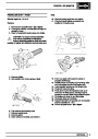
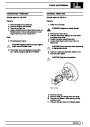
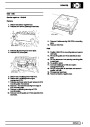
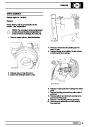
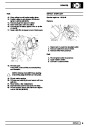
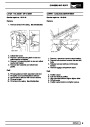
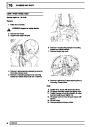
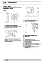
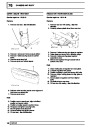
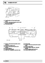
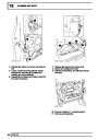
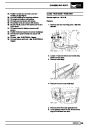
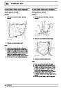
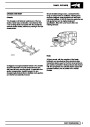
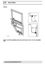
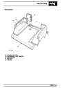
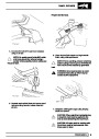
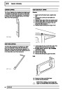
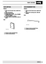
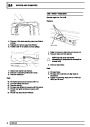
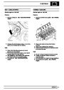
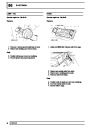
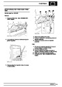
Timing chain cover
The timing chain cover is cast and machined aluminium alloy and is attached to the cylinder head by a bolt at the
RH top of the cover and by a stud and nut at the LH top of the cover. Eight screws are used to attach the timing
chain cover to the front of the engine block. The timing cover is located to the cylinder block front face by two
dowels.
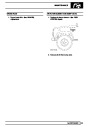
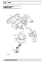
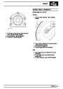
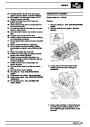
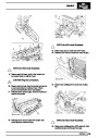
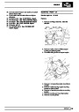
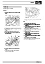
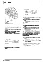
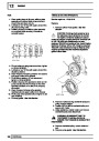
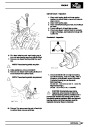
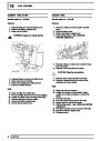
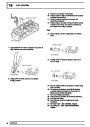
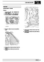
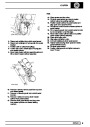
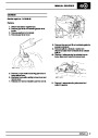
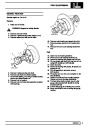
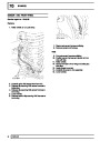
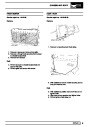
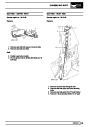
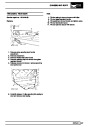
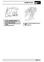
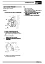
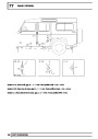
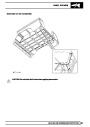
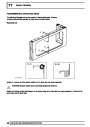
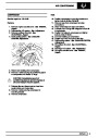
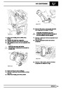
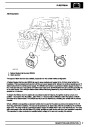
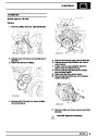
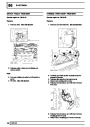
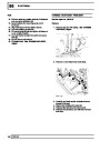
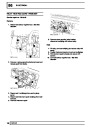
A viscous fan is attached to an idler pulley at the front of the engine block. The fan bearing is located on a shaft
and held in place by a circlip and a bearing flange, the inner race of the fan bearing is an interference fit on the
shaft. The fan idler pulley is attached to the bearing hub by three bolts and the fan itself is secured to the pulley
and bearing shaft by a left-hand threaded nut.
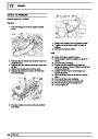
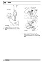
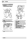
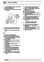
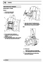
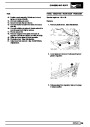
The front of the crankshaft passes through a hole in the lower part of the timing cover. An oil seal is pressed into a
recess in the front of the timing cover to seal the interface between the front of the crankshaft and the timing
cover.
A stub pipe is fitted to the front RH side of the timing cover which is used to attach the oil drain pipe from the
vacuum pump by means of a hose and spring clip.
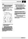
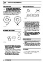
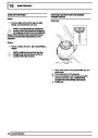
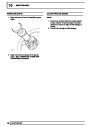
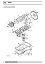
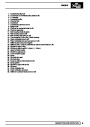
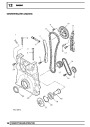
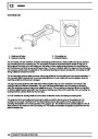
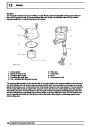
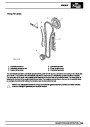
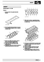
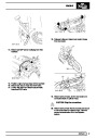
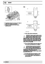
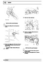
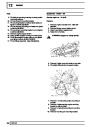
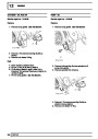
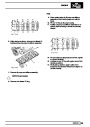
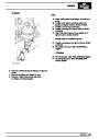
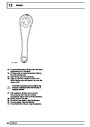
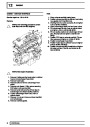
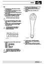
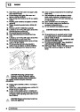
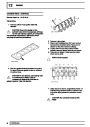
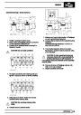
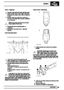
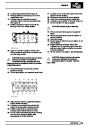
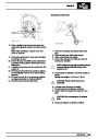
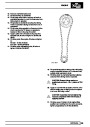
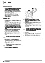
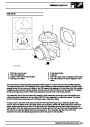
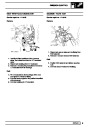
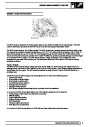
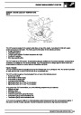
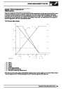
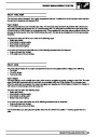
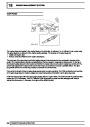
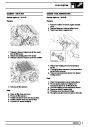
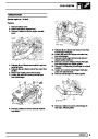
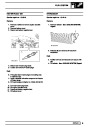
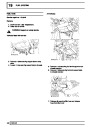
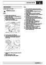
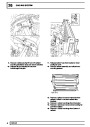
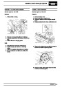
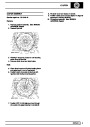
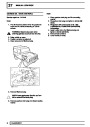
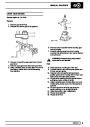
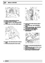
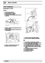
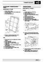
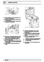
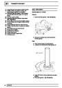
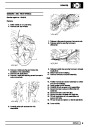
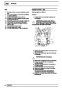
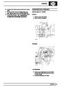
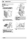
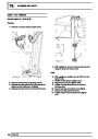
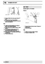
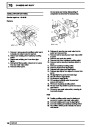
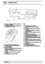
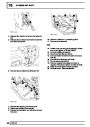
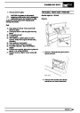
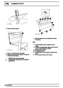
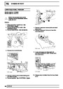
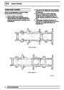
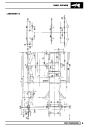
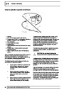
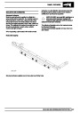
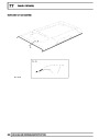
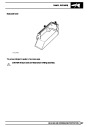
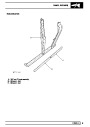
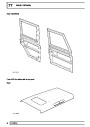
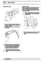
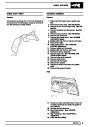
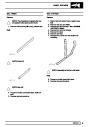
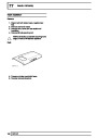
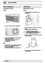
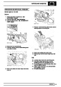
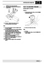
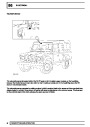
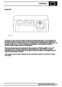
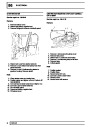
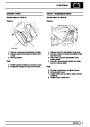
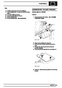
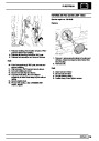
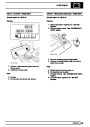
Timing chains
The timing chain between the camshaft and crankshaft sprockets is a duplex type, each chain having 56 links.
The timing chain is contained between a fixed plastic guide and an hydraulically adjustable plastic tensioner arm
which are attached to the front of the engine block.
To cope with the higher injection loads of the EU3 engine, the timing drive between the camshaft and crankshaft
has been upgraded. This requires thicker chain links to be used, therefore the individual pre EU3 and EU3
components are not interchangeable.
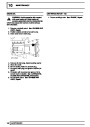
To distinguish between the two timing chains the links are different colours. A pre EU3 chain has blue links. An
EU3 chain has bronze links.
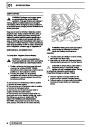
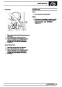
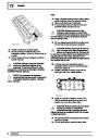
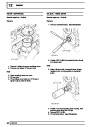
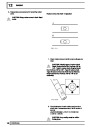
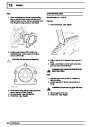
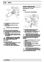
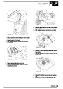
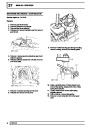
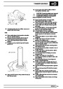
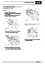
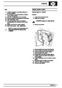
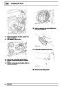
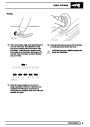
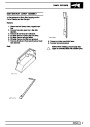
The oil pump timing chain is a single type and traverses the oil pump sprocket and the rear crankshaft sprocket.
The timing chains are oil lubricated, with oil being provided by a chain lubrication jet and from oil flow returning
back to the sump from the cylinder head. An oil hole is included at the front left hand side of the cylinder head
which supplies oil from the cylinder head oil galleries.
30
DESCRIPTION AND OPERATION
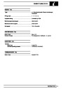
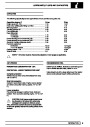
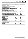
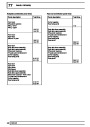
| Categories | Land Rover, Land Rover Defender |
|---|---|
| Tags | Land Rover |
| Model Year | 1999, 2000, 2001, 2002 |
| Download File |
|
| Document Type | Workshop Manual |
| Language | English |
| Product Name | Defender |
| Product Brand | Land Rover |
| Document File Type | |
| Publisher | landrover.com |
| Wikipedia's Page | http://en.wikipedia.org/wiki/Land_Rover |
| Copyright | Attribution Non-commercial |
(0 votes, average: 0 out of 5)