


26
COOLING SYSTEM
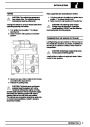
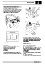
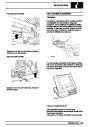
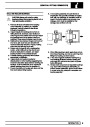
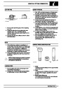
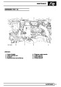
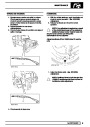
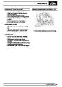
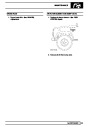
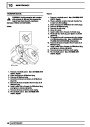
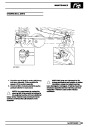
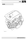
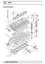
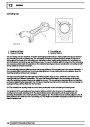
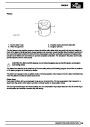
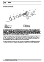
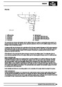
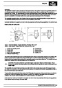
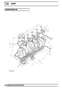
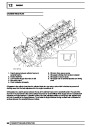
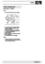
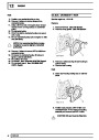
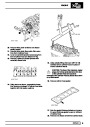
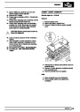
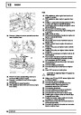
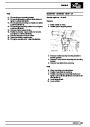
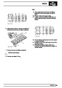
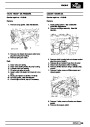
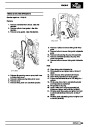
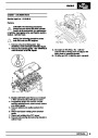
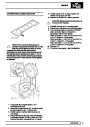
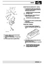
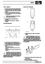
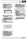
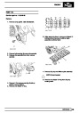
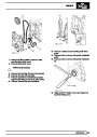
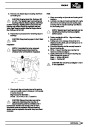
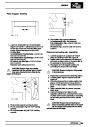
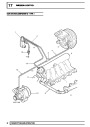
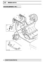
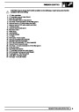
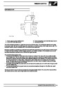
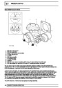
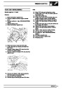
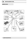
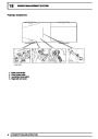
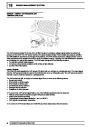
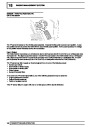
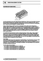
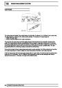
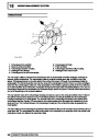
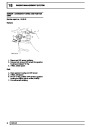
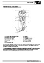
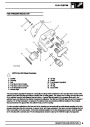
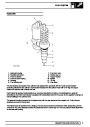
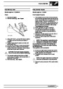
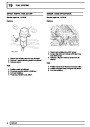
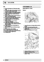
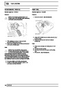
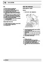
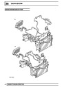
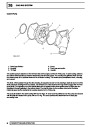
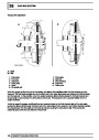
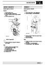
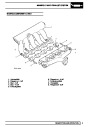
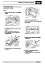
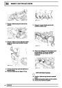
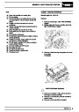
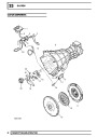
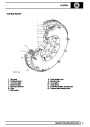
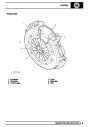
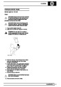
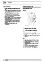
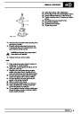
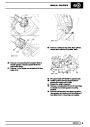
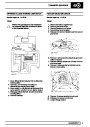
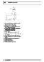
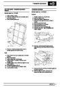
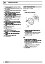
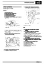
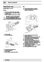
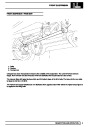
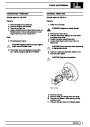
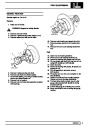
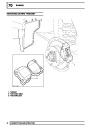
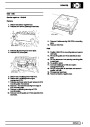
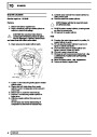
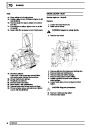
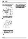
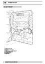
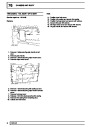
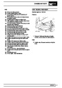
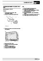
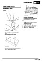
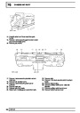
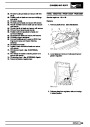
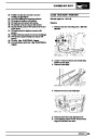
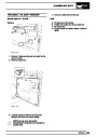
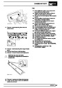
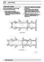
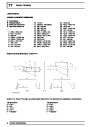
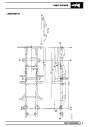
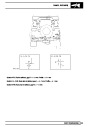
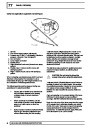
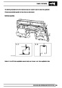
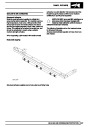
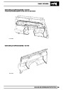
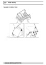
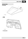
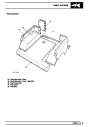
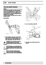
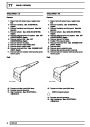
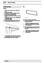
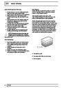
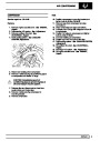
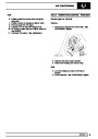
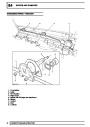
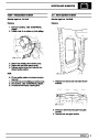
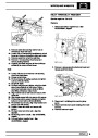
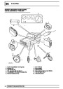
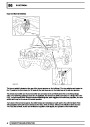
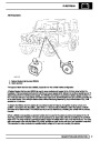
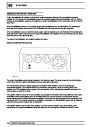
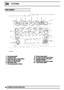
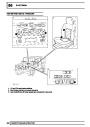
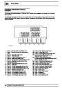
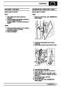
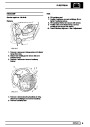
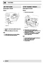
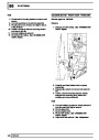
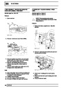
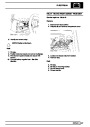
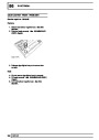
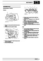
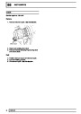
Coolant Pump
1.
2.
3.
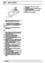
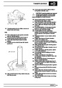
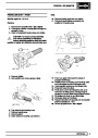
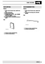
Drive lugs (hidden)
Housing
’O’ rings
4. Cover
5. Feed hose connection
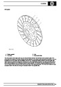
6. Impeller
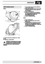
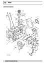
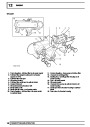
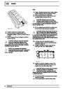
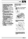
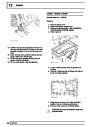
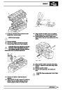
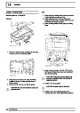
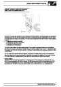
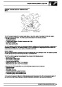
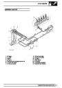
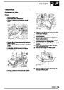
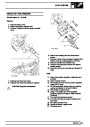
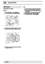
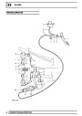
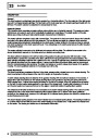
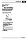
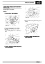
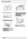
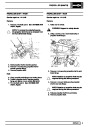
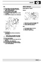
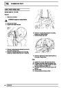
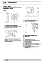
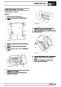
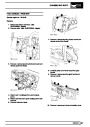
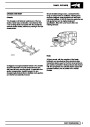
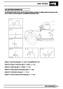
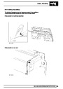
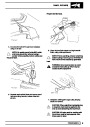
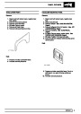
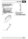
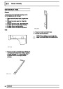
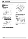
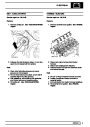
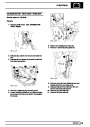
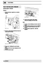
The coolant pump is attached on the left hand side of the engine, behind the PAS pump. A cast housing, bolted to
the cylinder block provides a common attachment point for both pumps. The housing has galleries which connect
the coolant pump to the cylinder block and the oil cooler housing. The coolant pump comprises a shaft, a housing
and a cover.
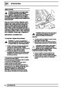
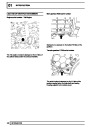
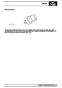
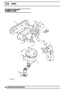
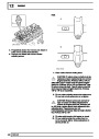
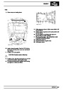
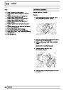
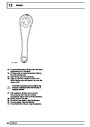
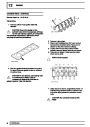
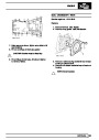
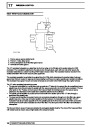
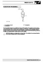
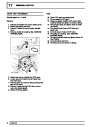
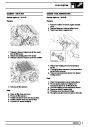
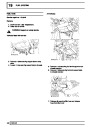
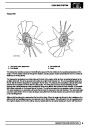
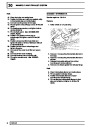
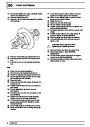
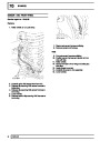
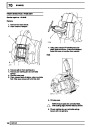
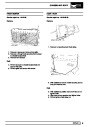
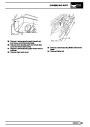
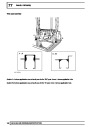
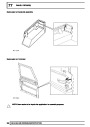
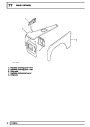
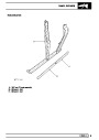
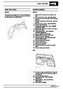
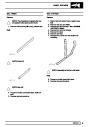
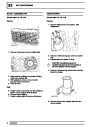
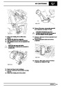
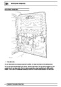
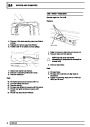
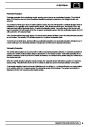
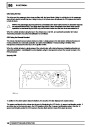
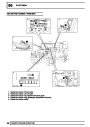
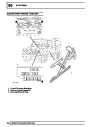
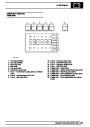
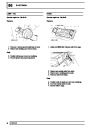
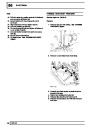
The shaft, which passes through the alloy housing, is supported at each end by bearings. Seals at each end of the
shaft protect the bearings from the coolant. The forward end of the shaft has two lugs which engage with the PAS
pump shaft. The opposite end of the shaft is fitted with an impeller which draws coolant from the feed pipe and
circulates it through galleries in the cylinder block. The shaft is driven by the auxiliary drive belt at the same
rotational speed as the crankshaft by a pulley attached to the PAS pump.
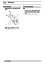
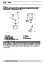
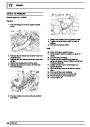
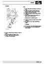
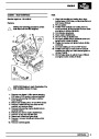
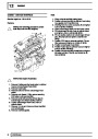
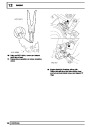
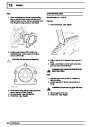
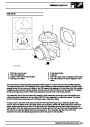
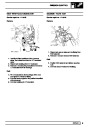
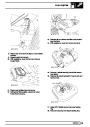
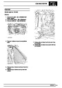
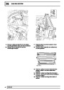
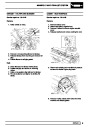
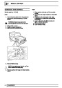
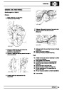
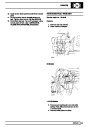
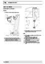
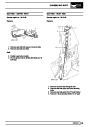
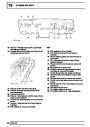
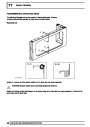
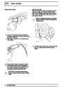
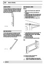
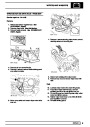
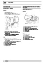
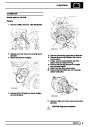
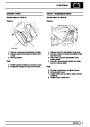
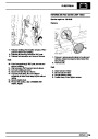
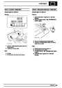
The pump is sealed in the cast housing with two ’O’ rings. An outer cover is positioned over the pump and secured
with six bolts and sealed to the pump with an ’O’ ring. The cover provides the attachment for the feed pipe
connecting hose.
8
DESCRIPTION AND OPERATION
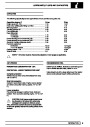
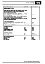
| Categories | Land Rover, Land Rover Defender |
|---|---|
| Tags | Land Rover |
| Model Year | 1999, 2000, 2001, 2002 |
| Download File |
|
| Document Type | Workshop Manual |
| Language | English |
| Product Name | Defender |
| Product Brand | Land Rover |
| Document File Type | |
| Publisher | landrover.com |
| Wikipedia's Page | http://en.wikipedia.org/wiki/Land_Rover |
| Copyright | Attribution Non-commercial |
(0 votes, average: 0 out of 5)