


77
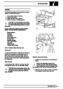
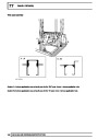
PANEL REPAIRS
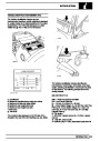
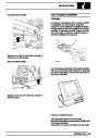
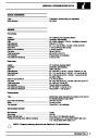
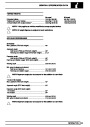
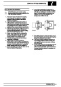
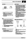
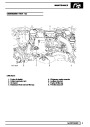
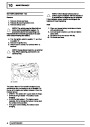
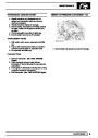
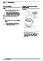
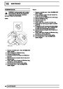
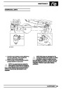
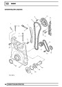
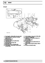
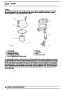
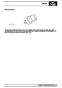
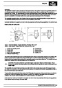
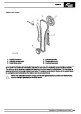
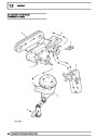
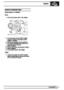
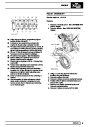
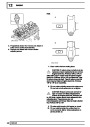
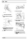
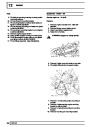
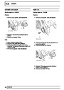
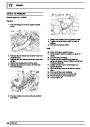
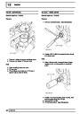
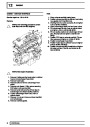
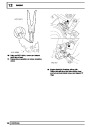
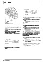
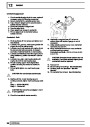
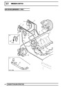
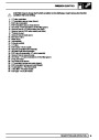
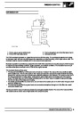
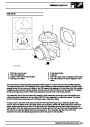
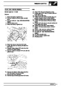
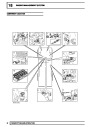
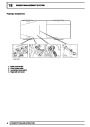
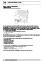
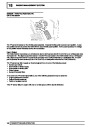
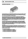
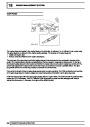
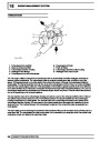
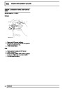
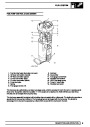
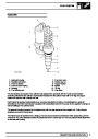
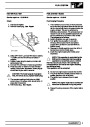
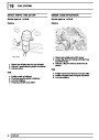
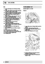
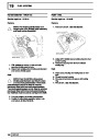
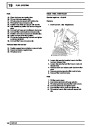
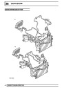
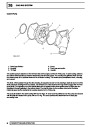
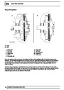
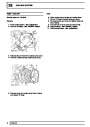
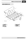
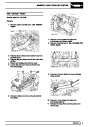
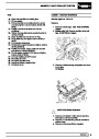
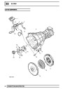
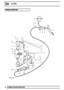
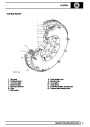
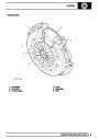
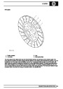
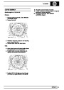
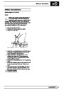
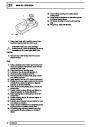
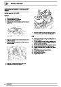
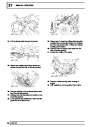
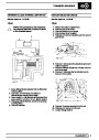
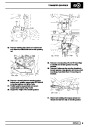
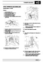
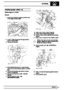
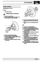
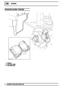
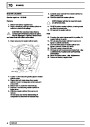
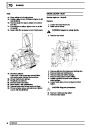
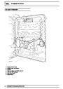
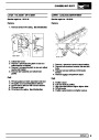
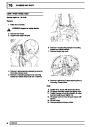
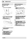
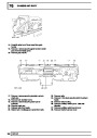
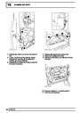
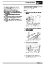
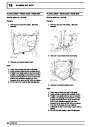
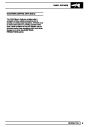
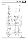
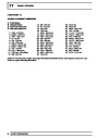
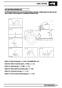
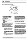
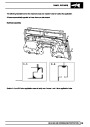
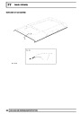
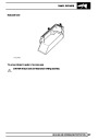
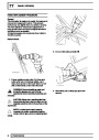
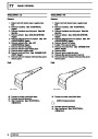
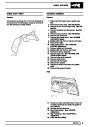
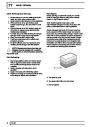
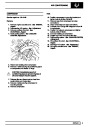
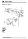
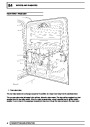
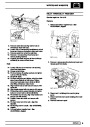
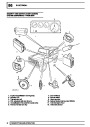
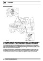
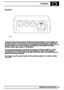
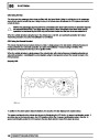
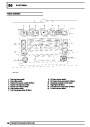
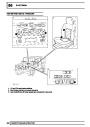
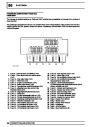
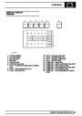
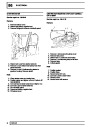
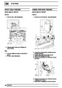
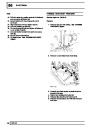
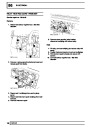
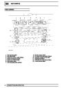
Cavity wax application equipment and techniques
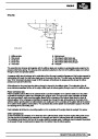
1.
2.
3.
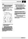
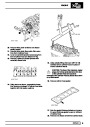
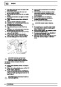
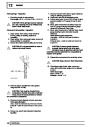
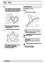
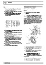
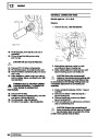
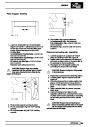
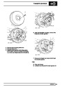
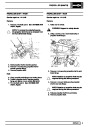
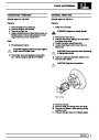
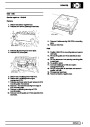
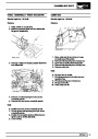
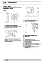
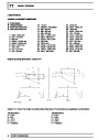
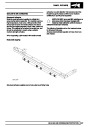
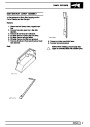
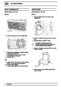
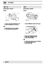
Air inlet
Flow control (spray pattern adjustment)
Pressure cup (1 litre [1.7 pt] capacity). Maximum
2
pressure 140 psi (9.7 bar, 9.8 kg/cm ).
Gun connector
Lance nipple connection
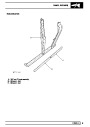
Flexible lance
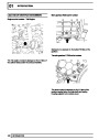
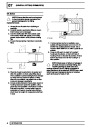
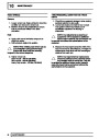
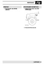
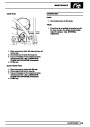
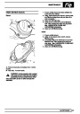
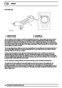
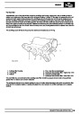
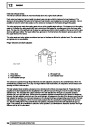
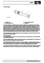
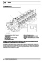
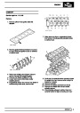
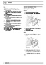
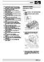
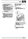
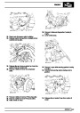
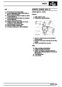
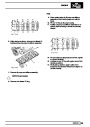
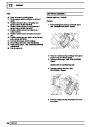
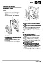
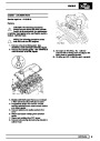
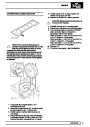
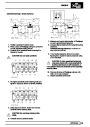
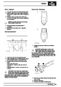
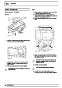
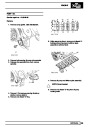
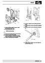
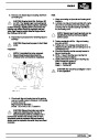
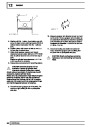
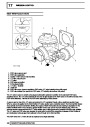
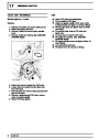
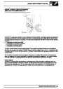
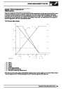
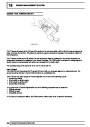
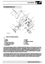
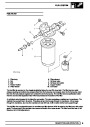
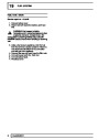
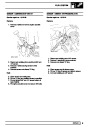
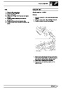
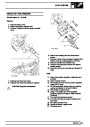
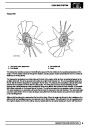
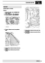
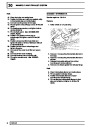
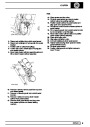
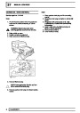
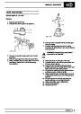
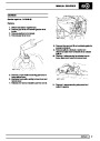
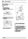
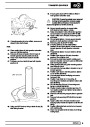
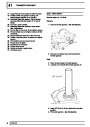
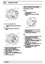
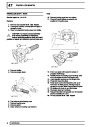
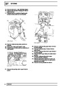
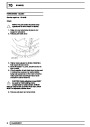
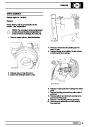
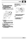
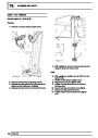
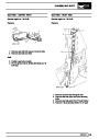
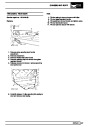
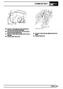
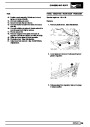
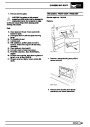
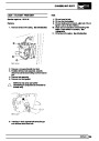
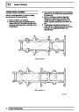
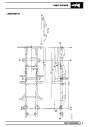
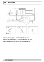
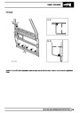
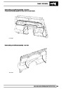
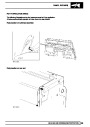
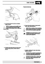
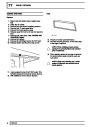
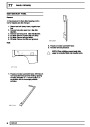
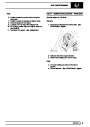
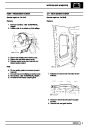
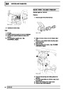
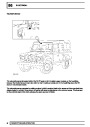
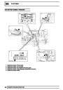
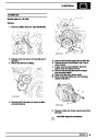
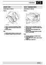
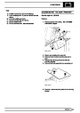
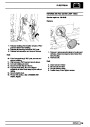
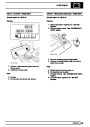
1100 mm (43.3in.) Rigid Lance:The nozzle on the
rigid lance produces a 360°circular spray pattern
combined with a forward-directed spray. Although wax
is distributed to all box section surfaces in a single
stroke, effective and complete coverage is best
achieved in long, straight structures and box section
cavities by spraying on both outbound and return
strokes of the lance.
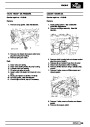
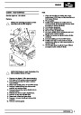
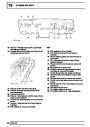
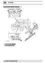
4.
5.
6.
7.
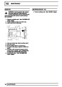
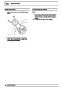
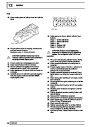
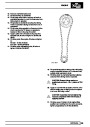
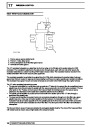
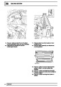
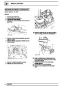
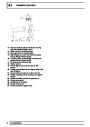
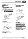
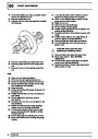
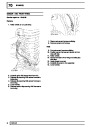
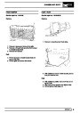
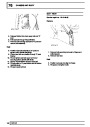
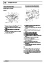
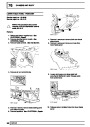
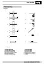
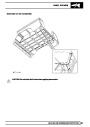
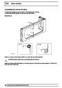
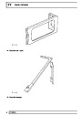
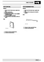
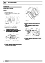
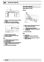
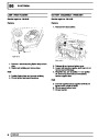
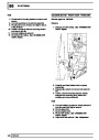
Rigid directional hook wand (forward cone spray
pattern)
8.
9.
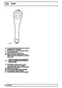
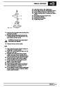
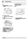
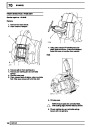
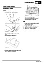
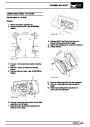
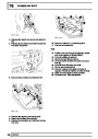
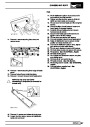
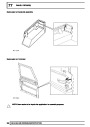
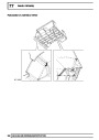
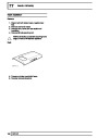
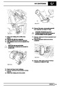
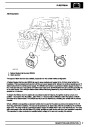
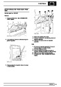
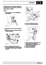
Flexible nylon 1100mm (43.3in.) lance with
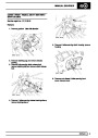
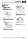
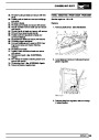
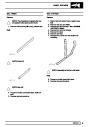
The rigid lance also provides the positional accuracy
required in shaped sections, by allowing visual
assessment.
360°spray pattern
Rigid 1100mm (43.3in.) lance with 360°spray
pattern
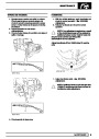
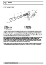
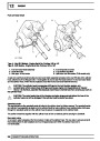
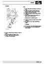
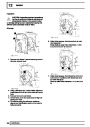
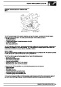
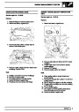
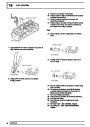
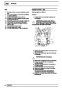
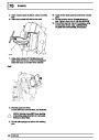
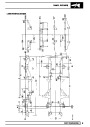
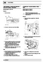
CAUTION: Do not force the lance into
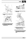
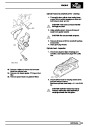
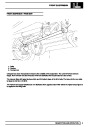
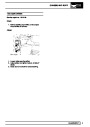
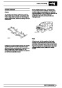
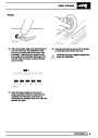
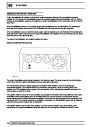
When re-treating wax-injected areas which have been
disturbed during repairs, it is necessary to use a
compressed air spray gun with integral pressure cup
and a selection of interchangeable lances.
access holes when using this attachment.
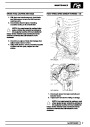
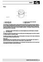
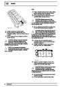
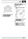
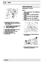
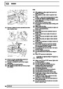
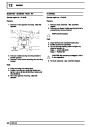
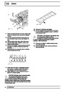
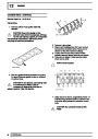
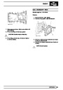
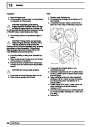
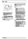
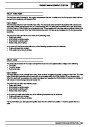
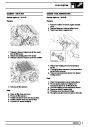
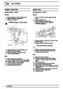
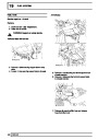
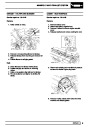
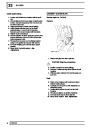
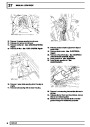
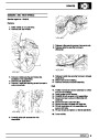
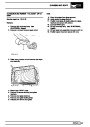
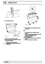
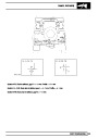
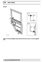
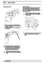
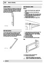
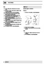
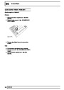
1100 mm (43.3in.) Flexible Nylon Lance:This lance
is similar in pattern to the rigid version, but provides
the additional penetration needed for curved sections
or in places where access is difficult. Its main
limitation is a lack of positional accuracy inside box
sections.
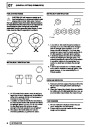
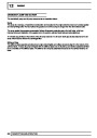
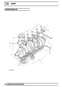
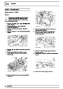
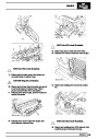
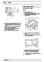
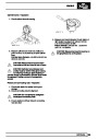
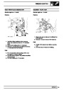
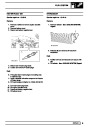
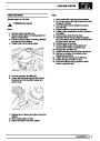
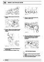
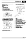
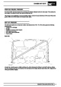
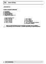
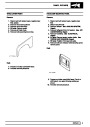
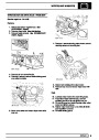
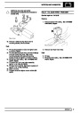
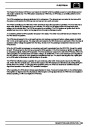
The following points must be observed during use,
according to the attachments fitted:
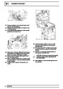
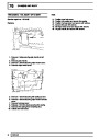
•
•
•
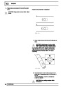
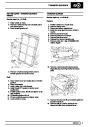
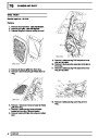
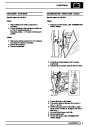
Use the rigid or flexible lance attachments
with 360°spray dispersal when treating
enclosed areas, to ensure maximum
coverage.
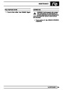
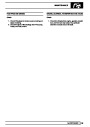
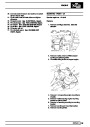
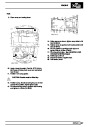
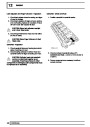
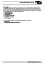
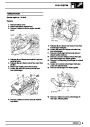
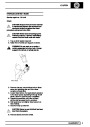
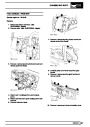
Carry out spraying on the outward stroke of the lance.
Withdraw the lance slowly to ensure sufficient
coverage. DO NOT withdraw the lance too quickly.
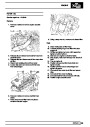
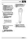
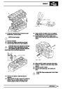
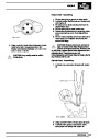
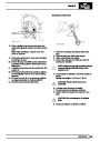
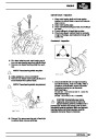
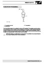
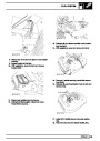
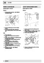
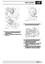
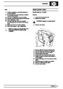
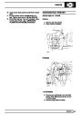
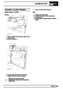
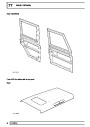
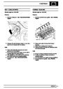
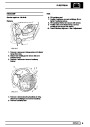
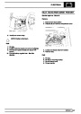
Where openings are restricted, use the
hook nozzle to provide a more directional
spray (e.g. inside narrow or short box
sections).
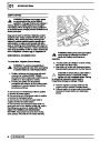
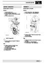
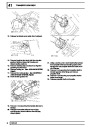
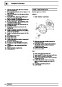
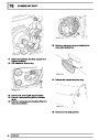
Keep the nylon tube of the lance away from the edges
of the access hole to eliminate abrasion and extend
the life of the tube. Take care to ensure that spraying
ceases just before the nozzle emerges from the
access hole. To assist this process, apply RED paint
to the final 30mm (1.2in.) of the nozzle.
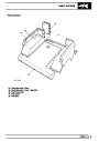
Spray exposed underbody surfaces directly
from the gun less lance attachment and
without disconnecting the fluid coupling.
6
SEALING AND CORROSION PROTECTION
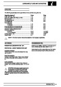
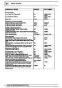
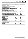
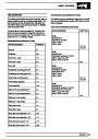
| Categories | Land Rover, Land Rover Defender |
|---|---|
| Tags | Land Rover |
| Model Year | 1999, 2000, 2001, 2002 |
| Download File |
|
| Document Type | Workshop Manual |
| Language | English |
| Product Name | Defender |
| Product Brand | Land Rover |
| Document File Type | |
| Publisher | landrover.com |
| Wikipedia's Page | http://en.wikipedia.org/wiki/Land_Rover |
| Copyright | Attribution Non-commercial |
(0 votes, average: 0 out of 5)