


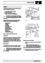


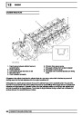


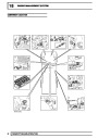


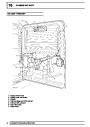


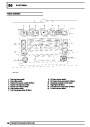


ENGINE
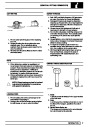
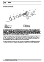
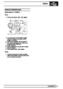
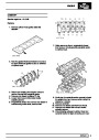
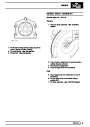
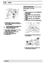
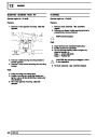
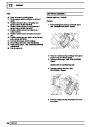
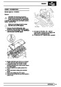
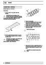
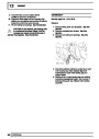
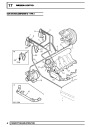
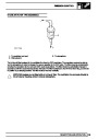
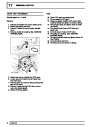
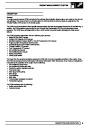
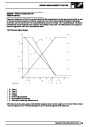
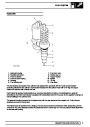
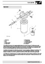
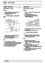
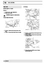
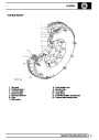
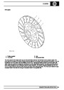
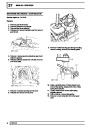
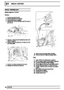
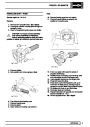
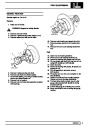
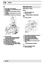
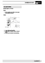
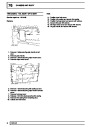
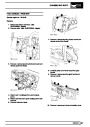
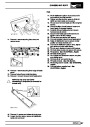
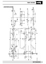
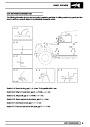
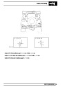
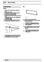
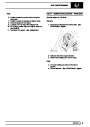
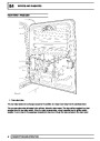
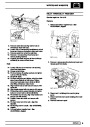
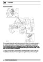
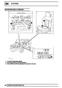
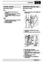
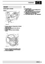
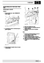
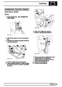
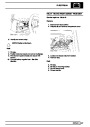
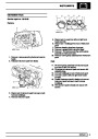
Piston ring gaps - Checking
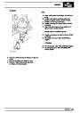
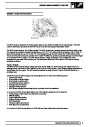
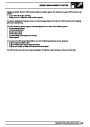
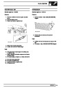
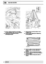
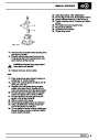
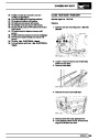
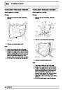
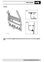
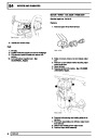
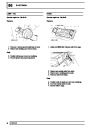
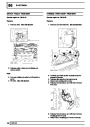
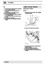
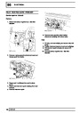
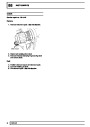
5.
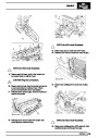
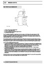
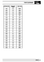
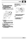
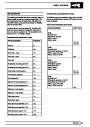
Check piston ring to groove clearance:
1st compression ring - Not measured
2nd compression ring = 0.050 to 0.082 mm
(0.02 to 0.003 in)
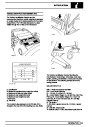
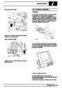
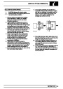
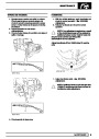
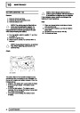
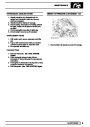
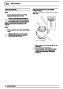
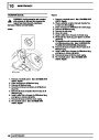
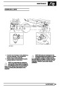
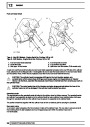
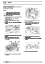
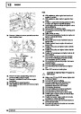
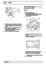
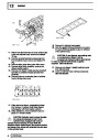
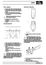
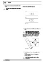
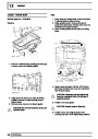
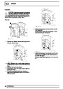
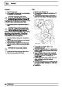
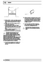
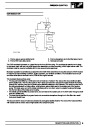
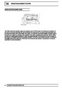
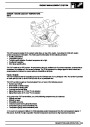
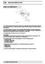
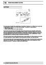
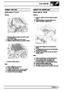
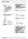
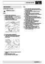
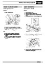
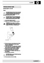
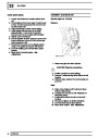
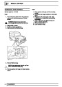
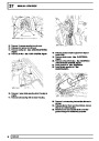
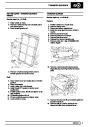
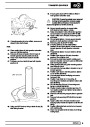
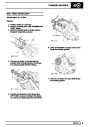
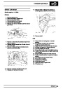
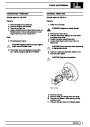
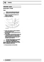
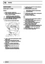
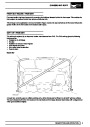
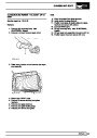
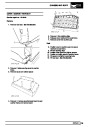
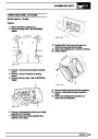
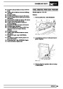
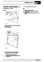
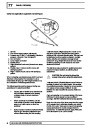
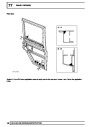
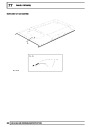
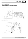
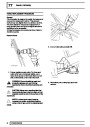
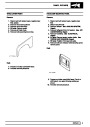
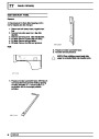
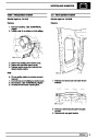
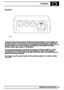
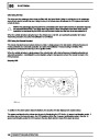
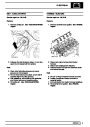
1.
Insert new compression and oil control piston
rings in turn into No. 1 cylinder bore 30 mm (1.25
in) from top of bore and check ring fitted gaps;
ensure rings are kept square to bore when
checking gaps.
Oil control ring = 0.050 to 0.082 mm (0.02 to
0.003 in)
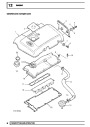
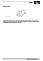
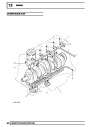
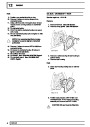
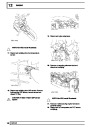
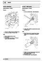
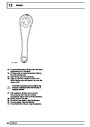
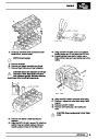
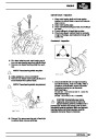
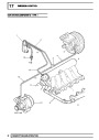
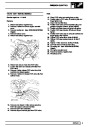
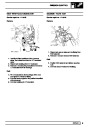
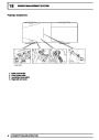
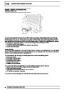
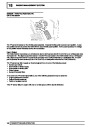
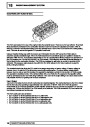
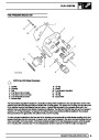
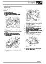
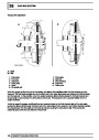
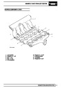
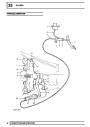
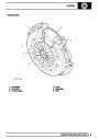
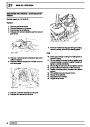
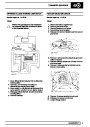
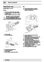
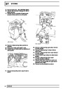
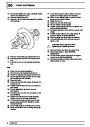
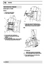
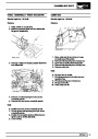
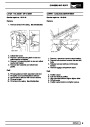
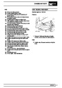
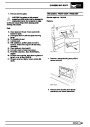
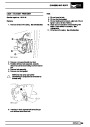
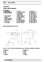
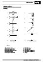
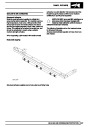
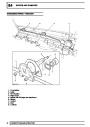
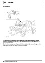
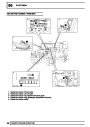
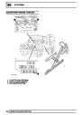
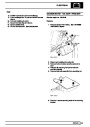
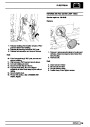
Pistons and connecting rods - Assembling
1st compression ring fitted gap = 0.30 to 0.40
mm (0.012 to 0.016 in)
2nd compression ring fitted gap = 0.40 to 0.60
mm (0.016 to 0.024 in)
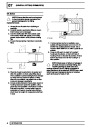
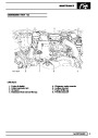
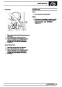
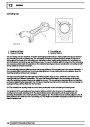
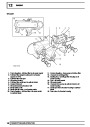
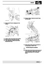
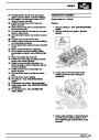
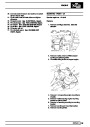
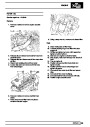
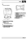
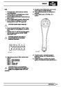
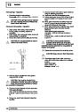
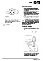
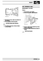
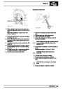
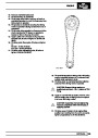
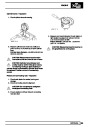
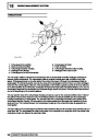
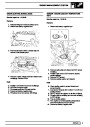
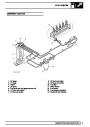
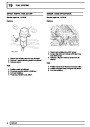
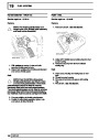
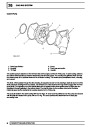
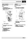
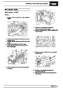
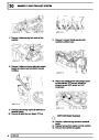
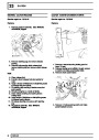
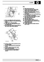
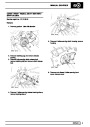
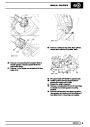
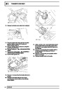
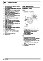
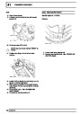
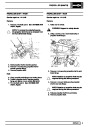
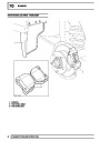
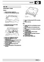
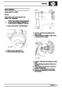
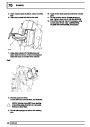
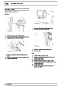
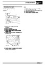
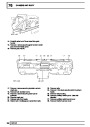
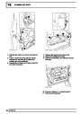
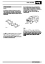
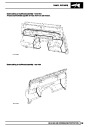
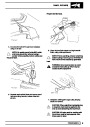
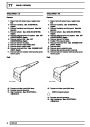
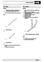
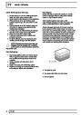
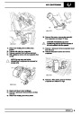
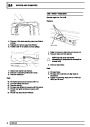
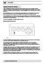
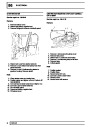
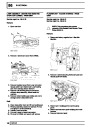
1. Lubricate gudgeon pin, gudgeon pin holes in
piston and small-end bush with engine oil.
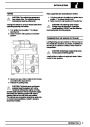
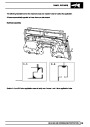
2. Position piston to its respective connecting rod
with arrow on piston crown on the same side as
the cast boss on the connecting rod.
Oil control ring fitted gap = 0.25 to 0.50 mm
(0.01
to 0.02 in)
Repeat for each cylinder bore in turn.
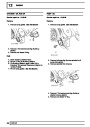
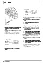
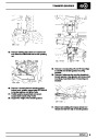
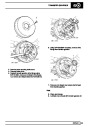
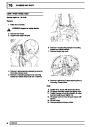
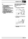
3. Fit gudgeon pin to its respective piston and
connecting rod; secure with new circlips.
CAUTION: Ensure rings are suitably
identified with the cylinder bore in which
they were checked and are fitted to the
CAUTION: Ensure circlips are fully seated
in their grooves.
piston for that bore.
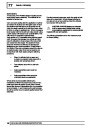
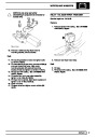
4.
5.
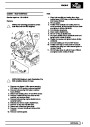
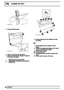
Repeat above procedures for remaining pistons.
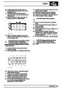
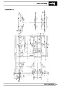
Lubricate piston rings and cylinder bores with
engine oil.
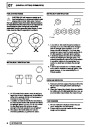
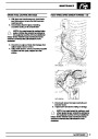
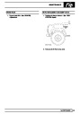
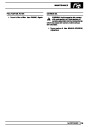
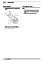
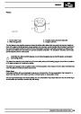
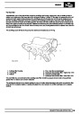
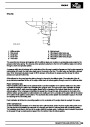
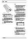
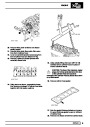
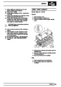
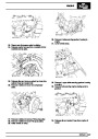
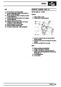
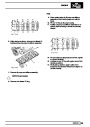
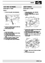
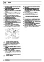
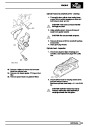
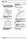
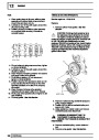
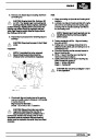
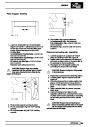
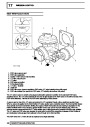
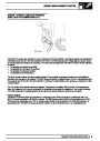
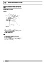
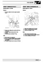
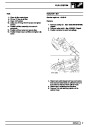
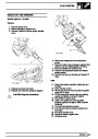
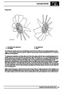
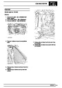
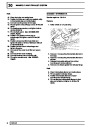
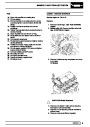
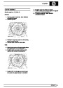
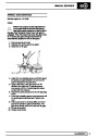
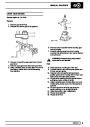
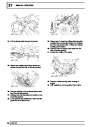
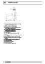
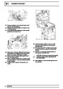
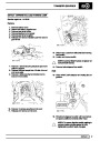
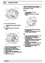
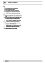
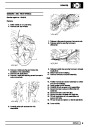
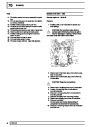
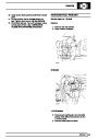
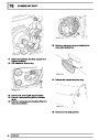
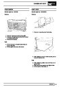
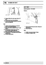
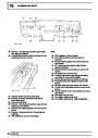
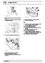
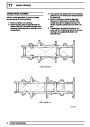
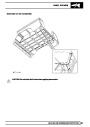
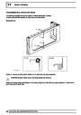
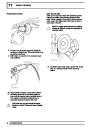
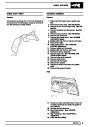
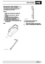
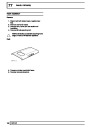
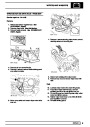
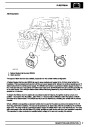
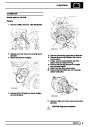
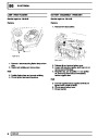
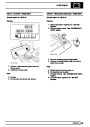
6.
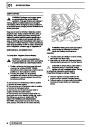
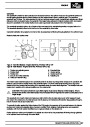
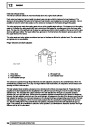
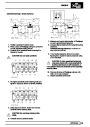
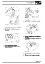
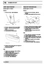
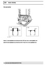
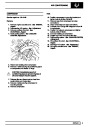
Check that rings are free to rotate, position ring
gaps at 120°to each other and away from the
thrust - LH side of piston - viewed from front of
piston.
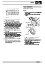
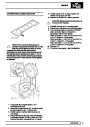
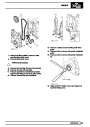
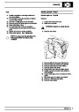
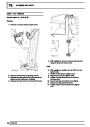
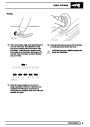
7.
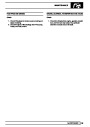
8.
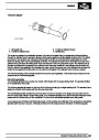
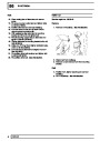
Using a suitable piston ring clamp, compress
piston rings.
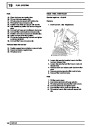
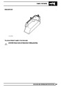
Insert connecting rod and piston into its
respective cylinder bore, ensuring that the arrow
on piston crown and the cast boss on connecting
rod are facing towards the front of the cylinder
block.
CAUTION: Ensure that connecting rod
does not contact cylinder bore or oil squirt
jet. Do not pull connecting rod fully down
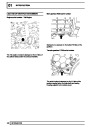
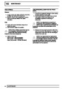
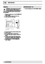
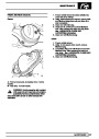
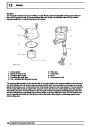
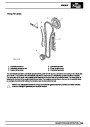
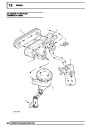
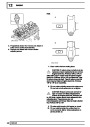
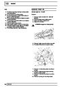
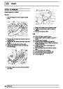
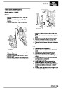
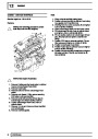
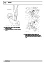
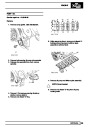
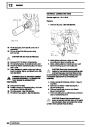
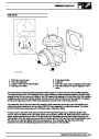
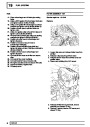
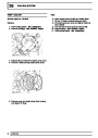
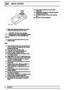
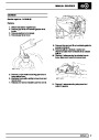
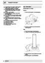
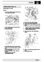
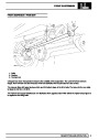
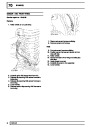
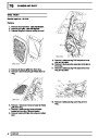
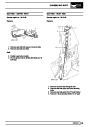
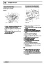
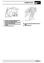
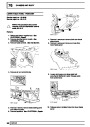
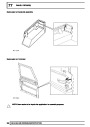
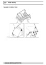
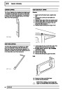
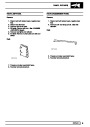
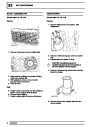
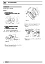
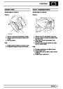
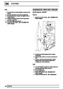
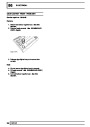
2.
3.
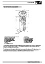
Fit oil control expander and ring to piston.
Fit 2nd compression ring with ’TOP’ marking
upwards.
cylinder bore at this stage.
4.
Fit 1st compression ring with ’TOP’ marking
upwards.
OVERHAUL
35
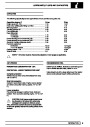
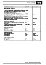
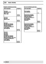
| Categories | Land Rover, Land Rover Defender |
|---|---|
| Tags | Land Rover |
| Model Year | 1999, 2000, 2001, 2002 |
| Download File |
|
| Document Type | Workshop Manual |
| Language | English |
| Product Name | Defender |
| Product Brand | Land Rover |
| Document File Type | |
| Publisher | landrover.com |
| Wikipedia's Page | http://en.wikipedia.org/wiki/Land_Rover |
| Copyright | Attribution Non-commercial |
(0 votes, average: 0 out of 5)