


17
EMISSION CONTROL
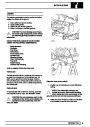
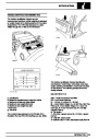
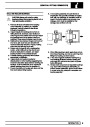
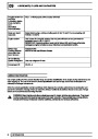
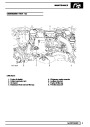
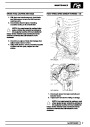
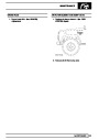
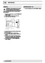
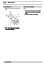
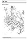
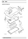
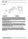
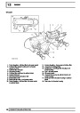
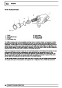
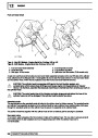
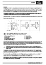
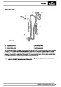
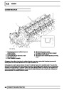
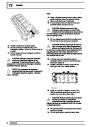
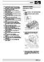
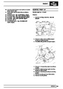
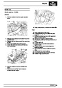
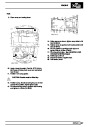
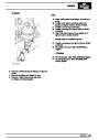
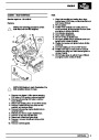
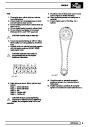
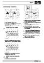
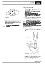
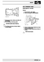
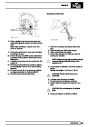
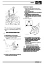
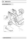
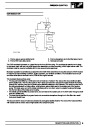
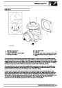
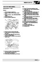
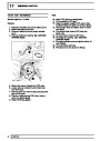
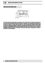
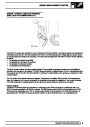
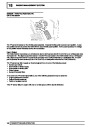
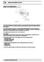
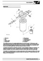
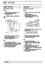
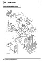
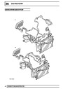
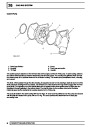
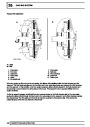
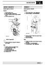
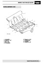
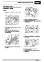
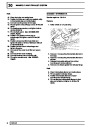
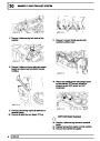
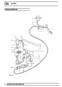
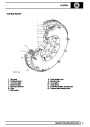
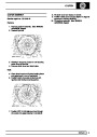
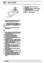
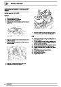
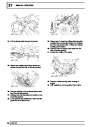
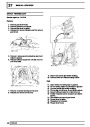
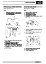
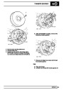
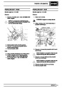
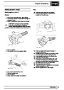
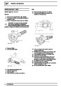
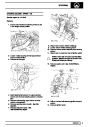
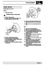
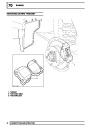
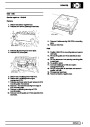
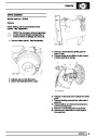
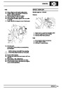
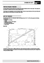
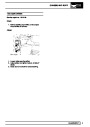
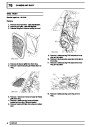
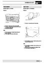
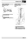
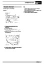
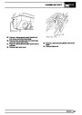
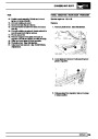
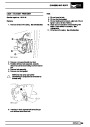
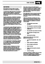
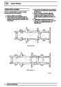
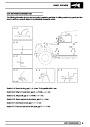
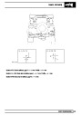
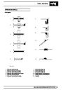
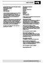
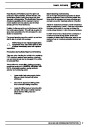
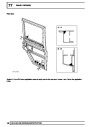
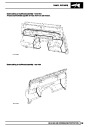
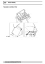
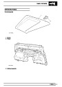
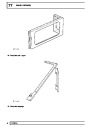
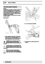
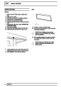
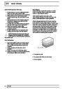
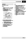
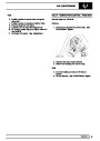
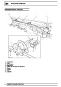
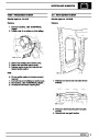
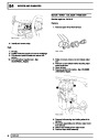
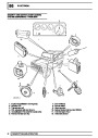
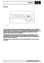
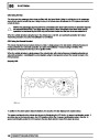
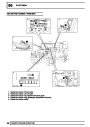
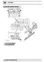
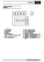
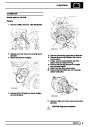
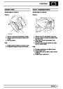
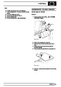
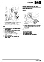
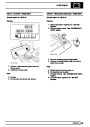
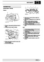
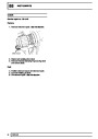
INLET THROTTLE (ILT) MODULATOR
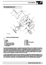
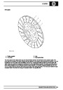
1.
2.
3.
4.
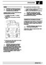
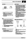
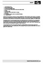
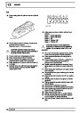
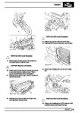
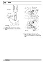
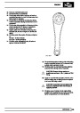
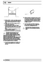
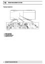
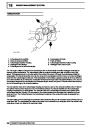
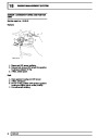
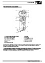
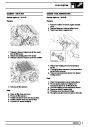
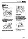
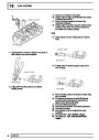
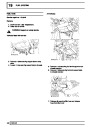
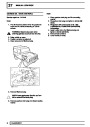
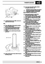
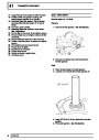
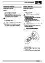
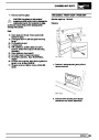
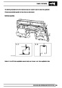
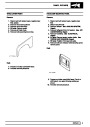
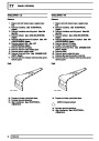
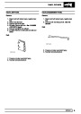
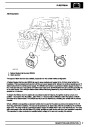
Port to vacuum source (white band)
Port to ILT valve (blue band)
Port to atmosphere via in-line filter (green band)
Harness connector (green)
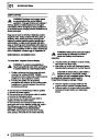
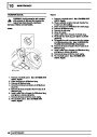
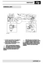
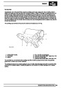
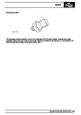
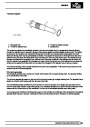
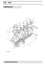
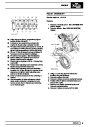
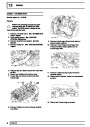
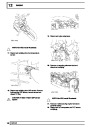
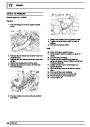
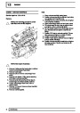
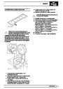
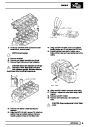
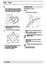
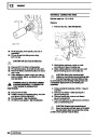
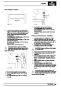
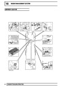
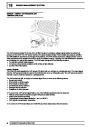
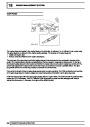
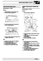
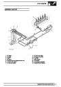
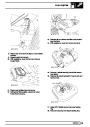
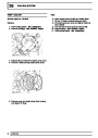
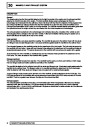
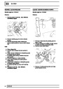
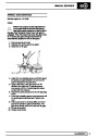
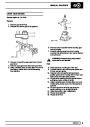
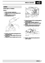
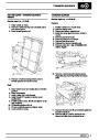
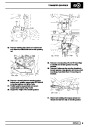
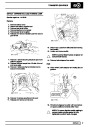
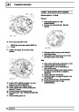
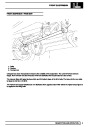
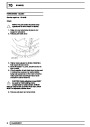
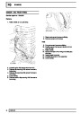
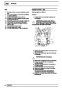
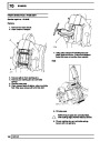
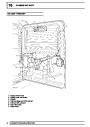
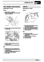
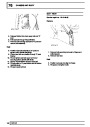
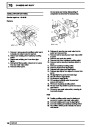
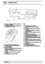
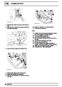
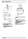
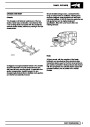
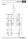
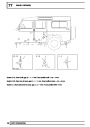
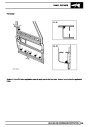
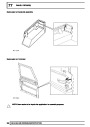
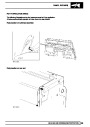
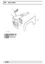
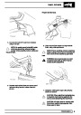
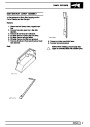
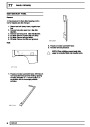
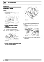
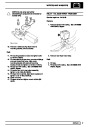
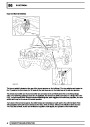
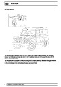
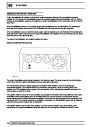
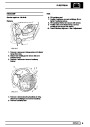
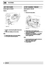
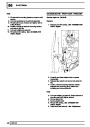
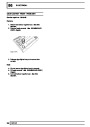
The ILT modulator is located on a plate fixed to the inner wing on the RH side of the engine below the EGR
modulator. The modulator is attached to the plate by two through-studs, each with two nuts which secure the
modulator assembly to a rubber mounting which helps to reduce noise. The modulator must be mounted in the
vertical orientation with the two vacuum ports uppermost.
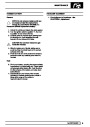
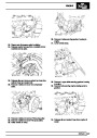
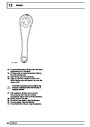
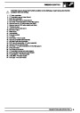
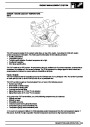
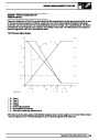
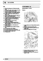
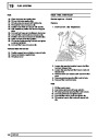
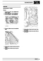
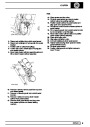
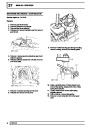
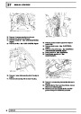
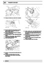
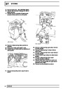
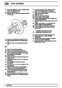
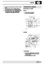
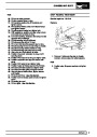
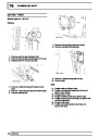
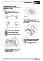
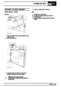
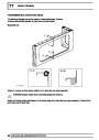
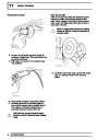
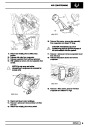
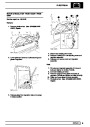
The modulator operation is controlled by a signal from the ECM which determines the required ratio of exhaust
gas to fresh inlet air needed in response to inputs relating to air flow and engine operating and ambient conditions.
The modulator has a green two-pin connector at its base to connect it to the ECM through the engine harness.
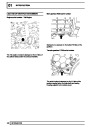
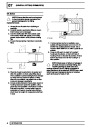
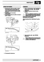
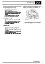
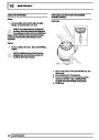
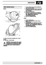
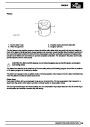
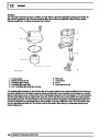
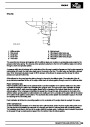
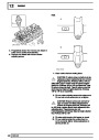
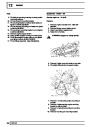
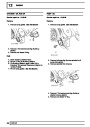
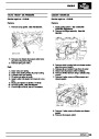
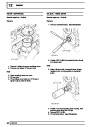
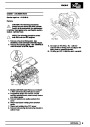
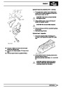
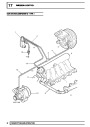
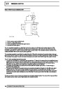
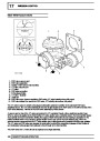
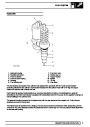
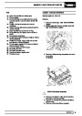
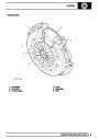
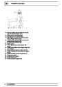
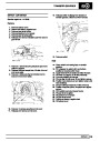
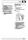
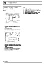
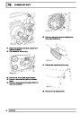
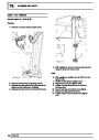
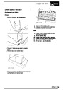
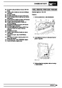
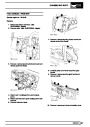
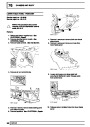
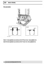
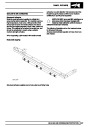
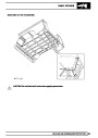
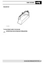
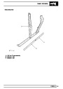
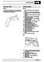
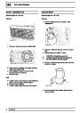
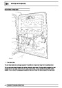
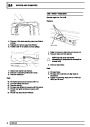
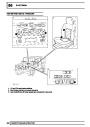
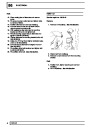
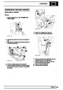
The ILT valve modulator features three ports:
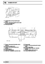
•
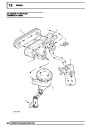
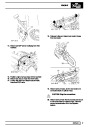
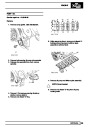
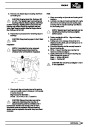
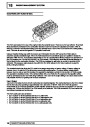
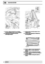
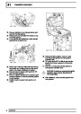
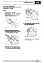
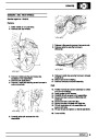
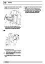
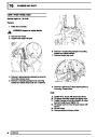
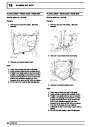
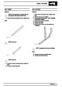
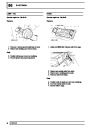
The top port is identified by a white band and connects to a ’T’-piece in the vacuum line via a small-bore brown
plastic hose where it is connected in parallel with the vacuum source line to the EGR valve modulator. The two
other ports on the ’T’-piece connect vacuum line hoses of black vinyl tubing between the vacuum pump
attached to the alternator and the brake-servo assembly attached to the bulkhead.
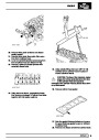
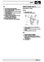
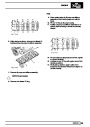
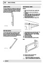
The middle port is identified by a blue band and connects to the suction port on the ILT valve through a
small-bore blue plastic hose.
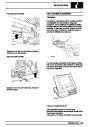
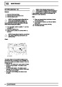
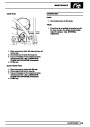
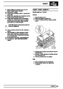
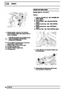
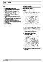
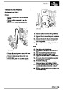
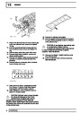
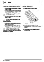
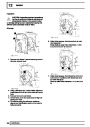
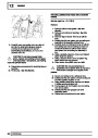
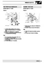
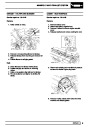
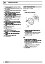
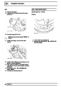
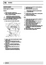
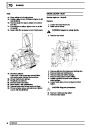
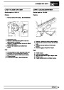
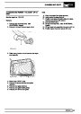
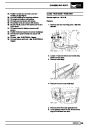
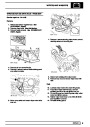
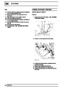
The lower port is identified by a green band and connects to atmosphere through an in-line filter via a green
plastic hose and a three-way connector positioned in-line between the modulators and the filter. The ILT
modulator hose is connected opposite to the two parallel ports at the three-way connector which connect the
vent lines to the EGR valve modulator and the in-line filter. The other port of the in-line filter vents directly to
atmosphere.
•
•
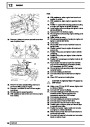
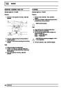
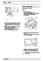
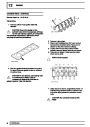
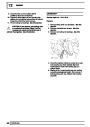
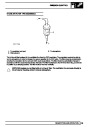
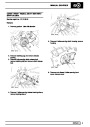
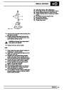
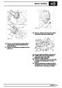
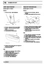
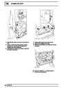
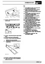
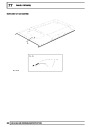
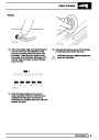
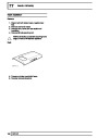
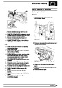
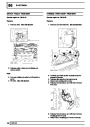
The blue and brown vacuum hoses are protected by corrugated plastic sheaths. The ends of the hoses are fitted
with rubber boots to ensure vacuum tight seals at the component ports.
10
DESCRIPTION AND OPERATION
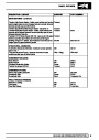
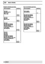
| Categories | Land Rover, Land Rover Defender |
|---|---|
| Tags | Land Rover |
| Model Year | 1999, 2000, 2001, 2002 |
| Download File |
|
| Document Type | Workshop Manual |
| Language | English |
| Product Name | Defender |
| Product Brand | Land Rover |
| Document File Type | |
| Publisher | landrover.com |
| Wikipedia's Page | http://en.wikipedia.org/wiki/Land_Rover |
| Copyright | Attribution Non-commercial |
(0 votes, average: 0 out of 5)