


18
ENGINE MANAGEMENT SYSTEM
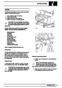
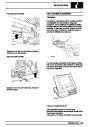
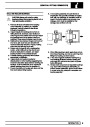
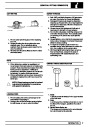
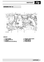
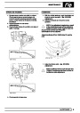
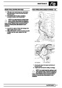
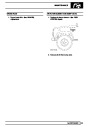
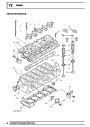
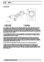
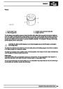
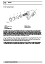
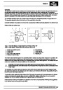
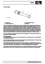
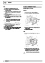
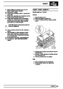
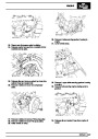
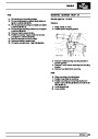
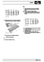
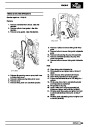
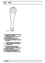
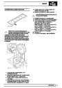
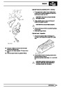
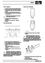
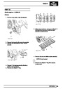
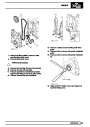
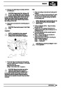
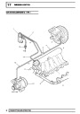
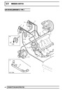
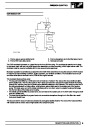
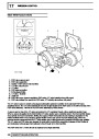
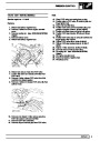
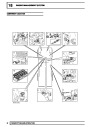
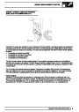
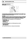
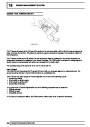
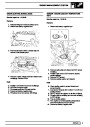
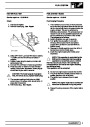
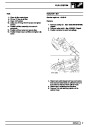
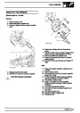
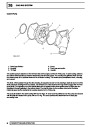
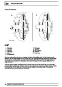
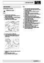
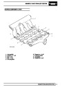
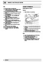
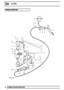
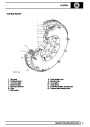
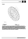
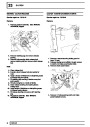
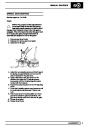
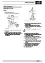
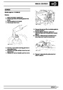
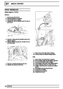
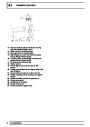
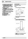
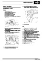
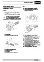
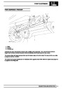
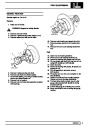
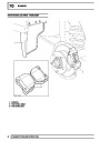
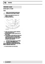
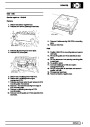
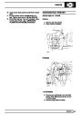
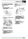
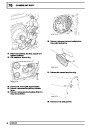
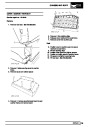
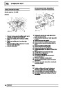
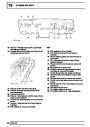
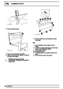
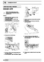
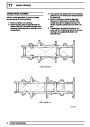
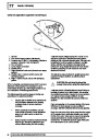
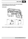
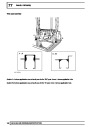
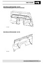
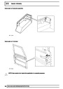
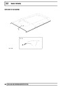
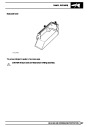
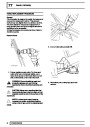
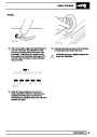
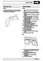
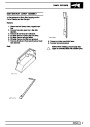
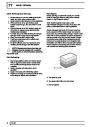
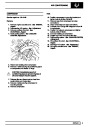
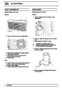
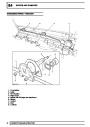
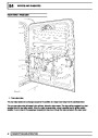
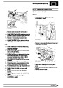
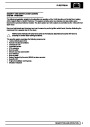
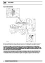
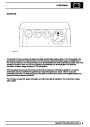
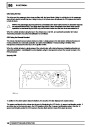
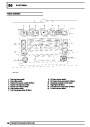
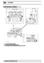
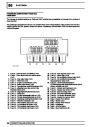
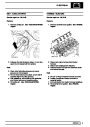
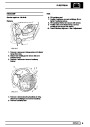
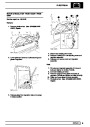
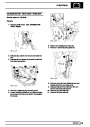
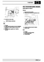
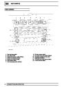
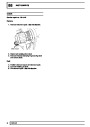
ELECTRONIC UNIT INJECTOR (EUI)
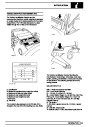
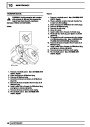
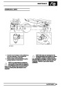
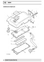
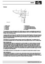
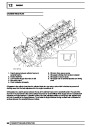
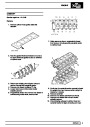
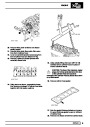
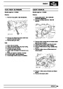
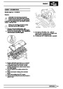
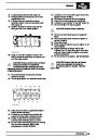
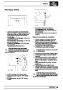
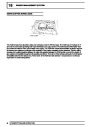
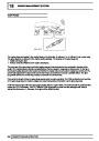
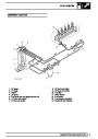
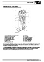
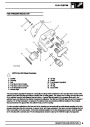
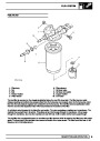
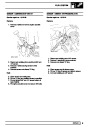
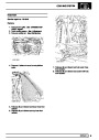
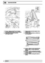
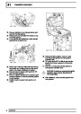
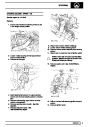
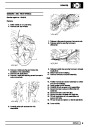
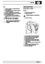
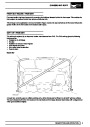
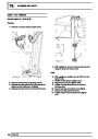
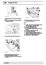
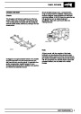
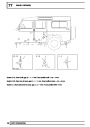
The EUI’s are located in the top of the engine inside the camshaft cover. There is one EUI per cylinder. They inject
finely atomised fuel directly into the combustion chamber. Each EUI has its own electrical connection, which is
linked to a common harness also located under the camshaft cover. Each of the EUI’s has its own 5 letter grading
code. This code is used so that greater EUI precision is achieved.
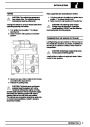
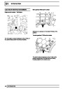
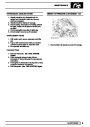
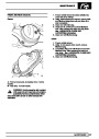
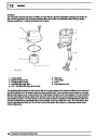
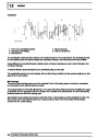
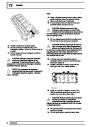
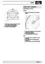
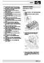
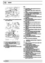
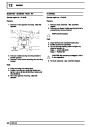
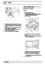
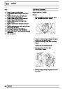
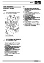
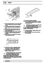
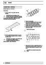
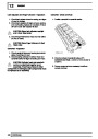
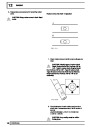
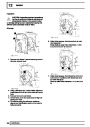
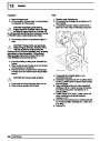
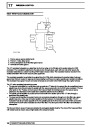
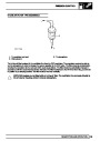
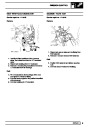
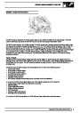
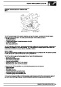
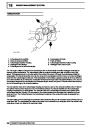
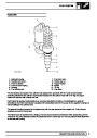
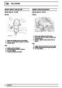
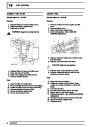
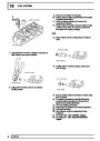
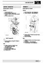
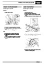
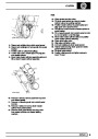
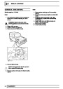
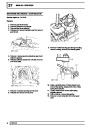
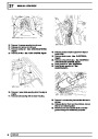
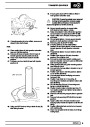
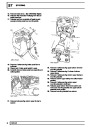
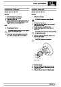
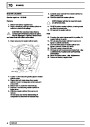
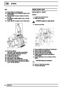
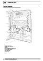
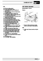
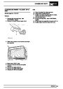
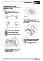
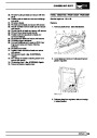
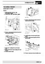
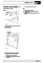
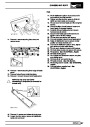
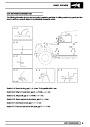
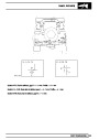
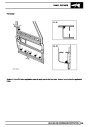
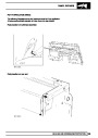
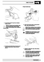
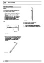
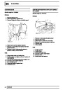
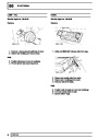
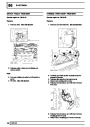
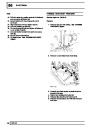
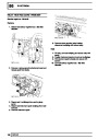
Using an injection timing map within its memory and information from the CKP sensor the ECM is able to
determine precise crankshaft angle. When the ECM determines the crankshaft speed and position it closes the
spill valve within the EUI. Fuel pressure rises inside the EUI to a predetermined limit of 1500 bar (22,000 lbf.in ) on
2
pre EU3 models, and 1750 bar (25,500 lbf.in ) on EU3 models . At this limit the pintle lifts off its seat allowing the
2
fuel to inject into the combustion chamber. The ECM de-energises the spill valve to control the quantity of fuel
delivered. This causes a rapid pressure drop within the EUI which allows the EUI return spring to re-seat the
pintle, ending fuel delivery.
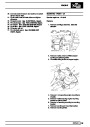
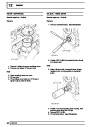
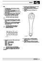
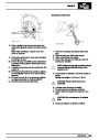
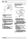
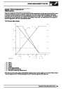
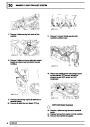
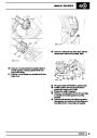
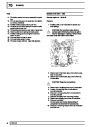
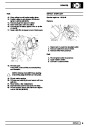
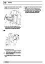
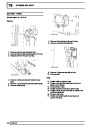
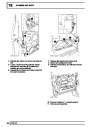
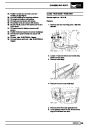
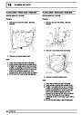
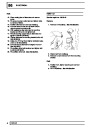
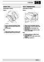
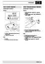
The electrical circuit that drives the EUI works in two stages depending on battery voltage. If battery voltage is
between 9 and 16 volts the EUI’s will provide normal engine performance. If however battery voltage falls to
between 6 and 9 volts on pre EU3 models, EUI operation is restricted to a limit of 2100 rev/min. On EU3 models,
EUI operation is restricted to idle. If the vehicle is fitted with a new ECM, the EUI grades for that specific vehicle
must be downloaded to the new ECM using TestBook. In the event of the engine failing to rev above 3000 rev/min
it is probable that the EUI grading has not been completed.
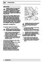
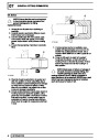
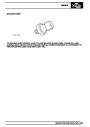
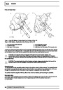
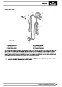
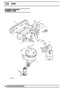
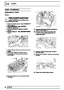
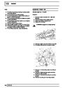
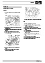
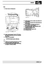
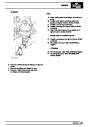
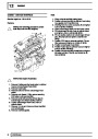
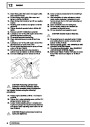
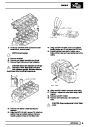
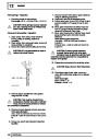
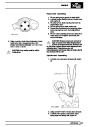
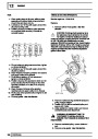
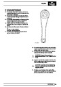
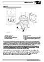
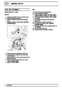
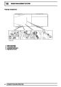
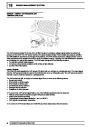
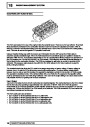
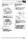
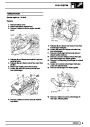
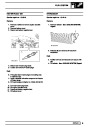
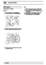
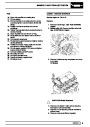
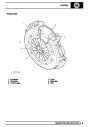
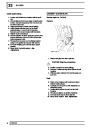
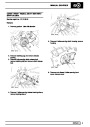
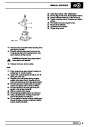
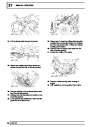
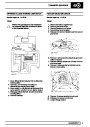
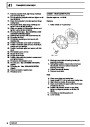
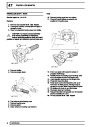
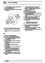
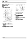
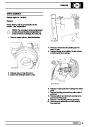
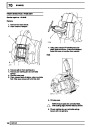
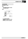
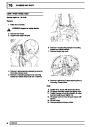
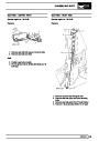
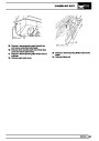
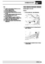
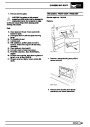
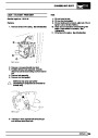
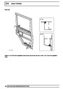
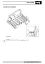
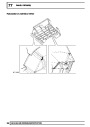
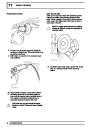
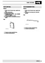
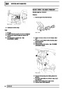
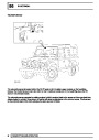
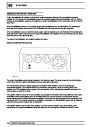
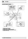
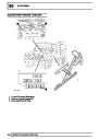
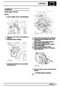
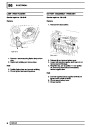
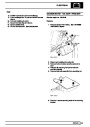
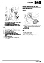
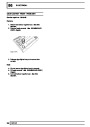
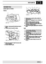
Input / Output
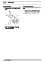
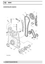
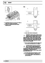
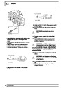
Input to the EUI takes the form of both mechanical and electrical signals. The mechanical input to the EUI is diesel
fuel via the fuel pump operating at approximately 4 to 5 bar (58 to 72 lbf.in
mechanically by an overhead camshaft to enable injection pressures of up to 1500 bar (22,000 lbf.in
models, and 1750 bar (25,500 lbf.in ) on EU3 models, to be achieved. The ECM controls the EUI’s to ensure that
2
). Each of the EUI’s is operated
2
) on pre EU3
2
fuel delivery is precise and as intended.
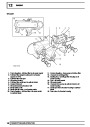
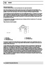
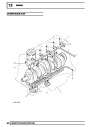
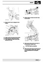
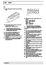
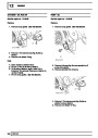
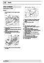
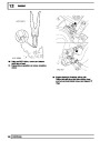
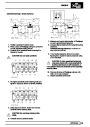
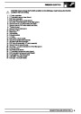
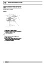
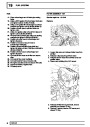
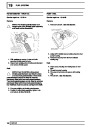
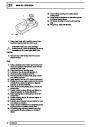
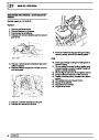
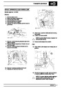
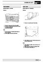
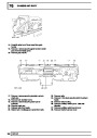
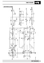
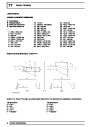
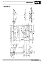
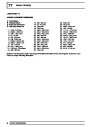
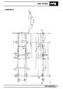
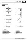
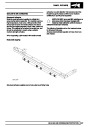
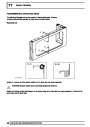
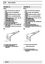
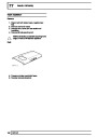
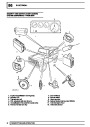
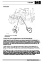
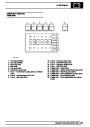
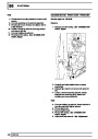
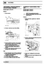
The EUI’s earth paths are as follows:
•
•
•
•
•
EUI 1 (C0522-1) via the ECM (C0158-25) on a yellow wire.
EUI 2 (C0523-1) via the ECM (C0158-26) on a yellow/brown wire.
EUI 3 (C0524-1) via the ECM (C0158-27) on a yellow/blue wire.
EUI 4 (C0525-1) via the ECM (C0158-24) on a yellow/red wire.
EUI 5 (C0526-1) via the ECM (C0158-1) on a yellow/purple wire.
18
DESCRIPTION AND OPERATION
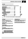
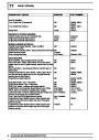
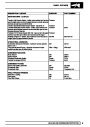
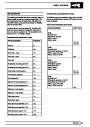
| Categories | Land Rover, Land Rover Defender |
|---|---|
| Tags | Land Rover |
| Model Year | 1999, 2000, 2001, 2002 |
| Download File |
|
| Document Type | Workshop Manual |
| Language | English |
| Product Name | Defender |
| Product Brand | Land Rover |
| Document File Type | |
| Publisher | landrover.com |
| Wikipedia's Page | http://en.wikipedia.org/wiki/Land_Rover |
| Copyright | Attribution Non-commercial |
(0 votes, average: 0 out of 5)