


V8i
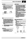
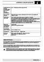
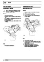
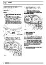
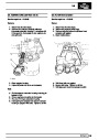
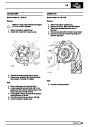
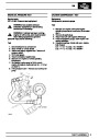
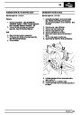
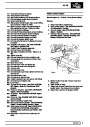
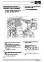
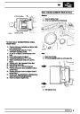
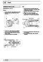
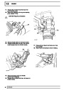
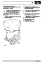
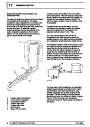
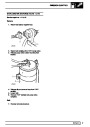
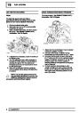
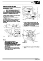
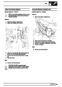
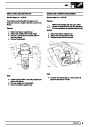
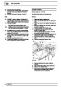
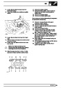
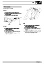
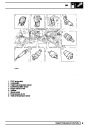
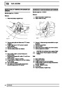
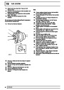
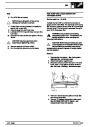
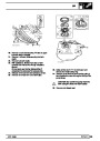
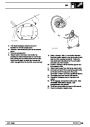
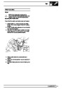
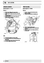
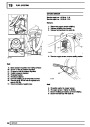
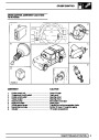
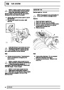
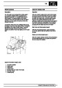
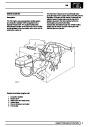
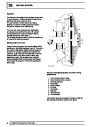
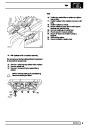
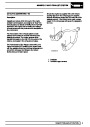
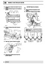
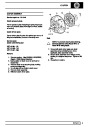
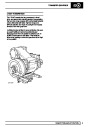
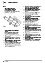
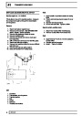
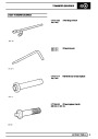
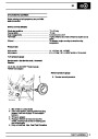
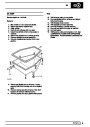
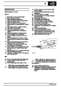
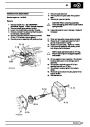
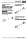
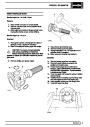
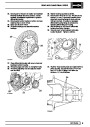
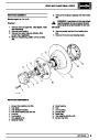
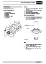
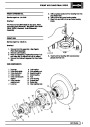
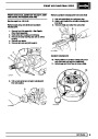
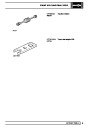
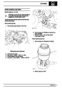
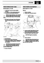
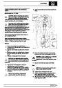
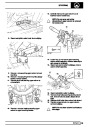
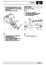
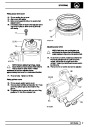
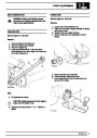
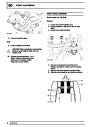
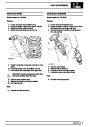
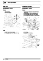
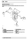
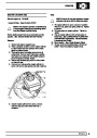
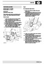
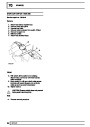
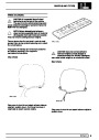
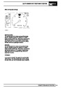
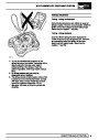
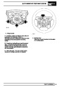
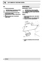
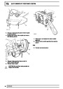
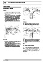
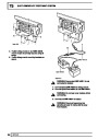
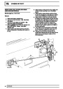
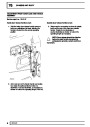
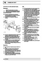
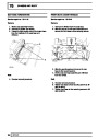
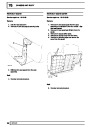
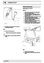
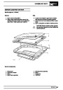
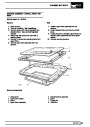
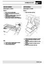
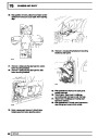
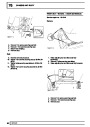
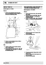
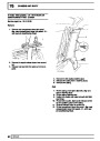
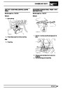
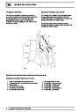
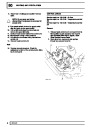
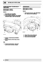
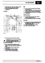
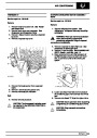
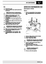
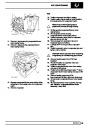
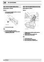
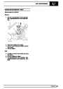
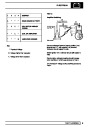
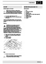
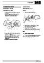
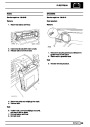
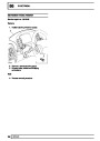
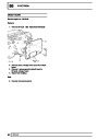
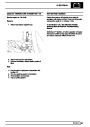
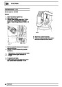
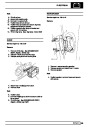
NOTE: Release bolts securing compressor
mounting bracket to engine and remove
bracket to enable temporary lifting eye
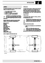
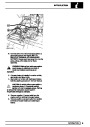
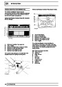
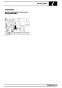
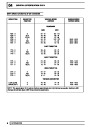
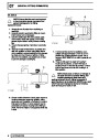
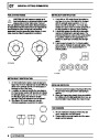
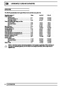
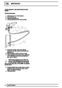
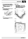
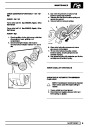
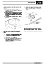
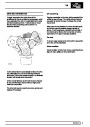
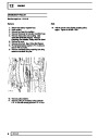
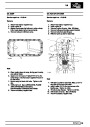
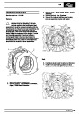
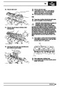
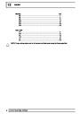
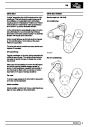
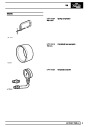
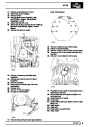
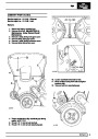
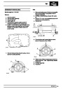
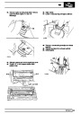
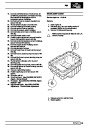
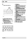
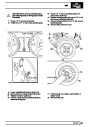
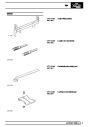
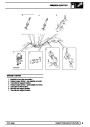
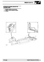
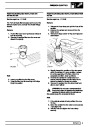
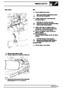
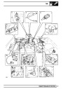
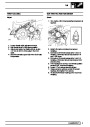
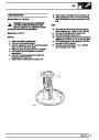
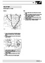
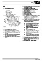
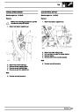
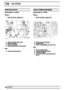
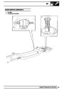
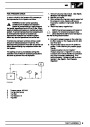
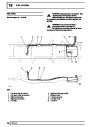
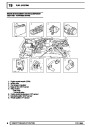
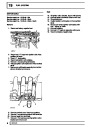
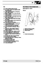
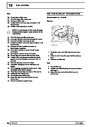
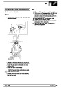
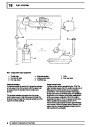
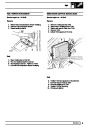
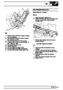
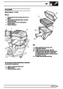
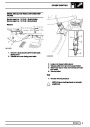
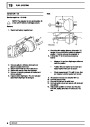
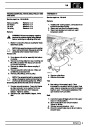
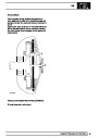
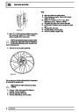
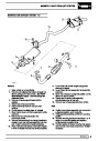
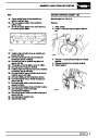
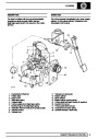
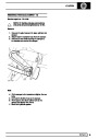
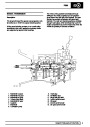
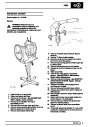
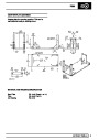
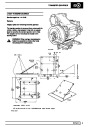
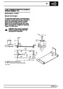
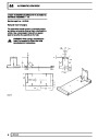
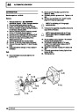
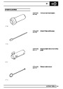
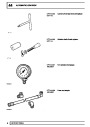
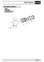
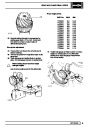
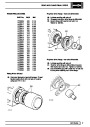
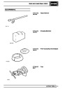
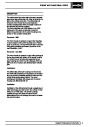
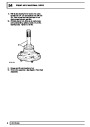
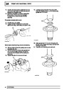
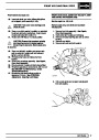
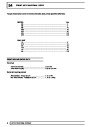
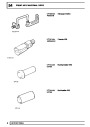
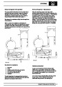
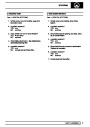
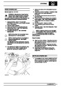
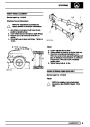
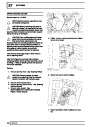
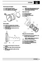
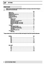
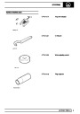
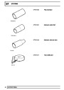
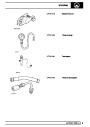
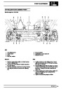
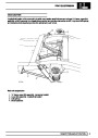
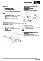
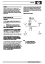
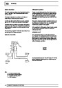
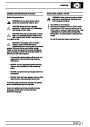
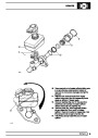
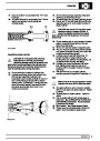
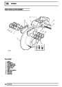
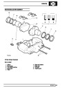
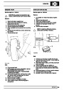
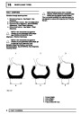
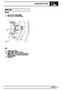
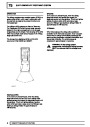
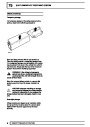
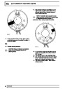
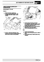
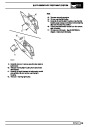
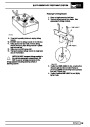
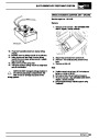
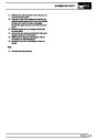
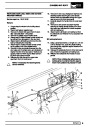
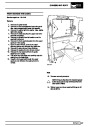
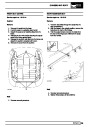
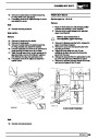
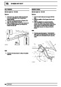
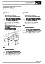
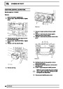
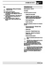
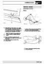
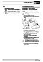
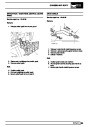
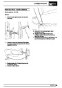
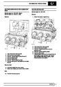
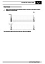
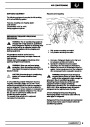
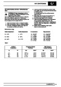
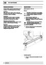
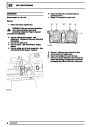
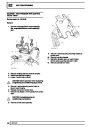
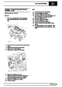
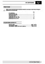
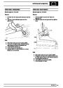
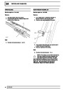
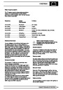
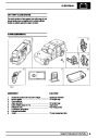
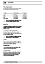
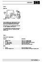
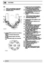
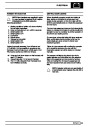
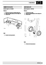
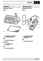
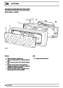
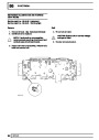
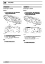
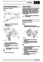
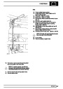
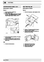
NOTE: All chain dimensions are measured
from end of lifting hook to end of last link
in chain.
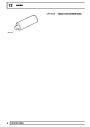
ETC 5964 to be fitted. Secure lifting eye to
mounting bracket fixing points with suitable bolts
of equivalent size, pitch and thread. Leave lifting
eye attached until engine is reinstalled in vehicle.
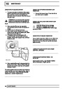
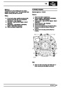
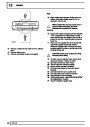
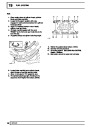
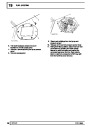
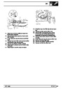
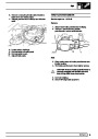
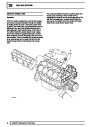
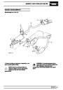
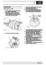
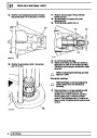
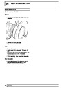
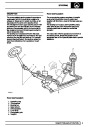
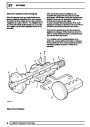
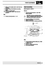
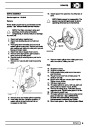
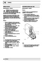
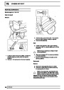
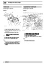
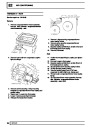
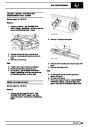
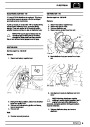
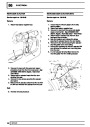
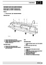
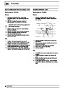
25. Fit chain lifting eye to a suitable engine hoist.
Raise hoist high enough to enable engine
mountings to be removed, and withdraw rubber
mountings.
15.
16.
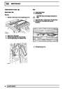
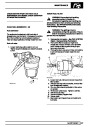
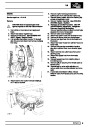
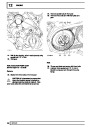
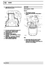
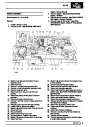
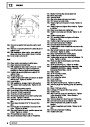
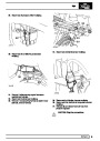
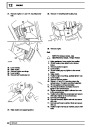
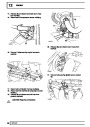
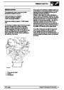
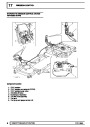
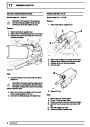
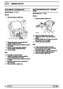
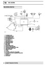
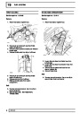
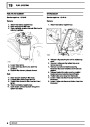
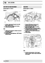
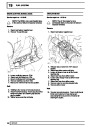
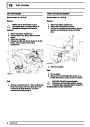
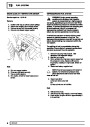
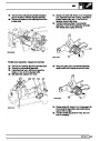
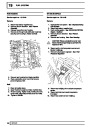
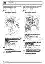
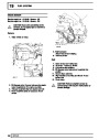
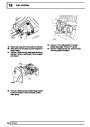
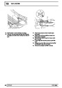
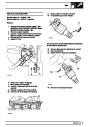
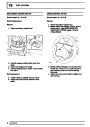
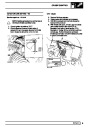
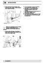
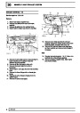
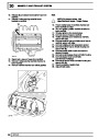
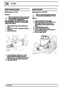
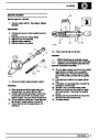
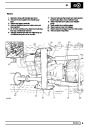
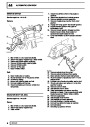
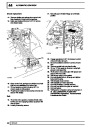
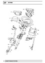
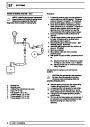
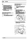
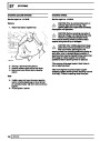
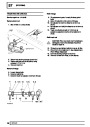
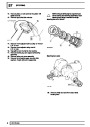
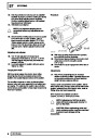
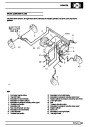
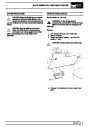
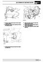
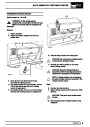
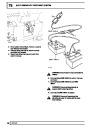
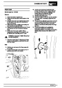
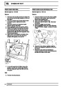
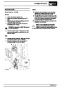
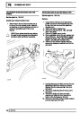
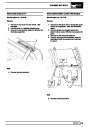
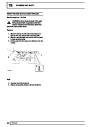
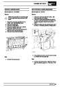
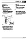
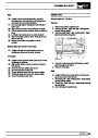
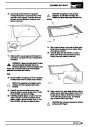
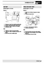
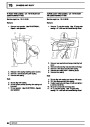
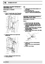
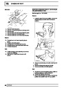
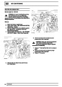
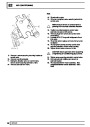
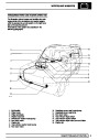
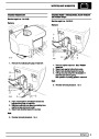
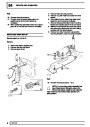
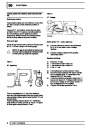
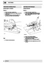
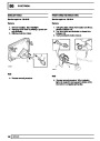
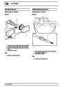
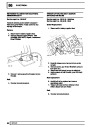
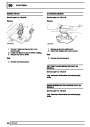
Place drain tray underneath vehicle.
Disconnect hose from reservoir to power
steering pump. Secure hose end above level of
fluid reservoir to avoid unnecessary loss of fluid.
Disconnect power steering pump to power
steering box hose. Seal hose and pump
openings with masking tape to prevent ingress of
dirt. Wipe away any fluid spillage from chassis or
steering box.
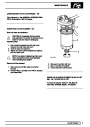
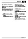
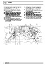
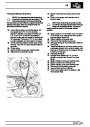
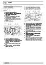
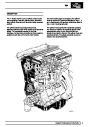
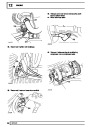
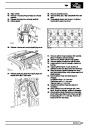
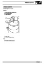
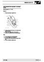
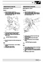
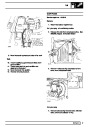
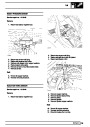
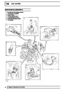
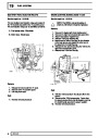
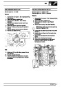
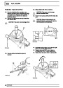
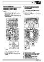
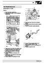
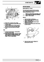
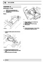
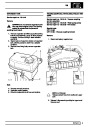
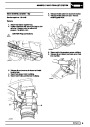
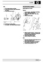
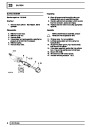
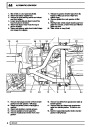
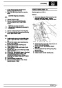
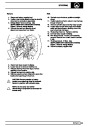
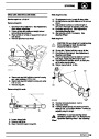
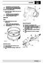
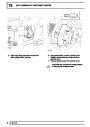
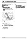
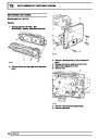
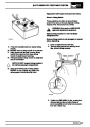
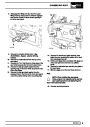
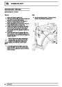
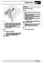
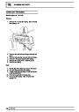
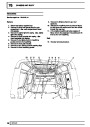
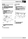
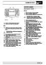
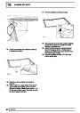
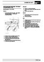
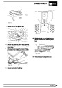
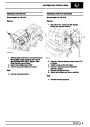
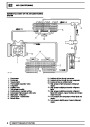
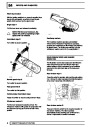
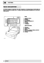
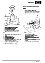
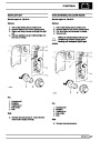
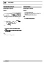
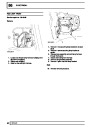
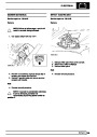
Disconnect fuel temperature and coolant
temperature sensor multi-plugs.
Disconnect leads from coil.
Identify each injector multi-plug for re-assembly
and disconnect plugs from injectors.
Manoeuvre harness from behind fuel rails and
place to one side clear of engine assembly.
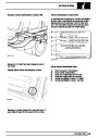
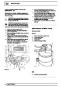
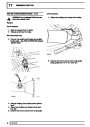
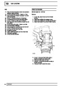
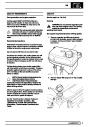
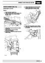
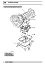
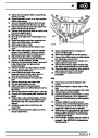
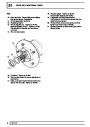
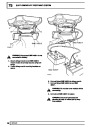
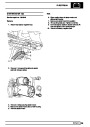
Remove two clamps securing gearbox oil cooler
pipes to engine block.
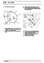
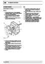
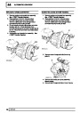
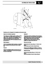
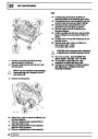
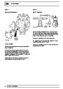
26. Lower hoist until engine rests securely on engine
mounting brackets. Remove lifting chains and
hoist.
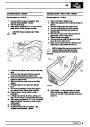
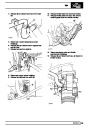
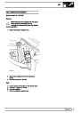
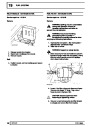
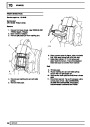
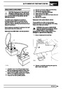
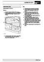
27. Disconnect two heater hoses located on top of
right hand rocker cover.
28. Remove ground strap from rear of left hand
cylinder head. DO NOT remove from retaining
clip.
29. Remove all electrical harnesses from retaining
clips at rear of engine.
30. Remove transmission breather pipes from
retaining clip on rear lifting eye.
31. Remove top two bolts securing bell housing to
cylinder block.
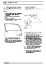
32. Raise front of vehicle, lower vehicle on to axle
stands.
33. Remove bell housing bottom cover. Remove
gasket from bell housing face.
17.
18.
19.
20.
21.
22.
23.
24.
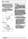
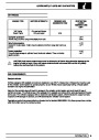
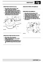
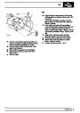
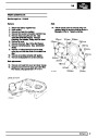
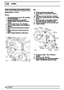
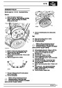
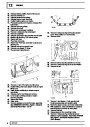
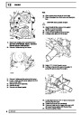
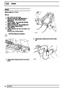
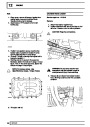
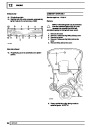
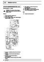
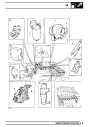
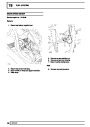
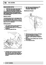
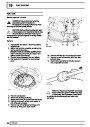
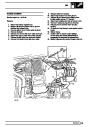
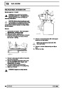
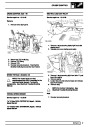
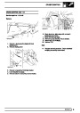
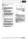
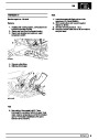
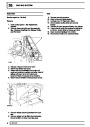
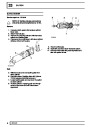
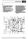
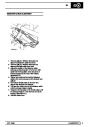
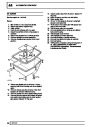
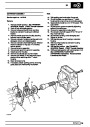
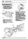
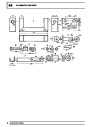
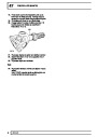
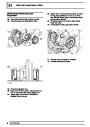
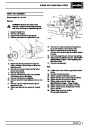
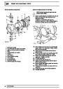
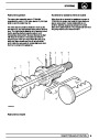
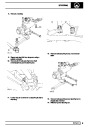
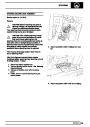
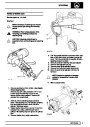
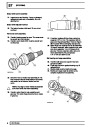
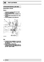
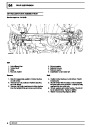
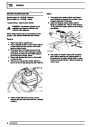
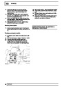
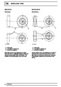
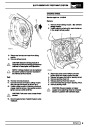
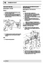
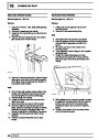
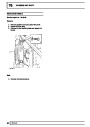
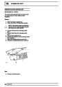
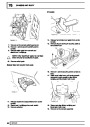
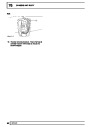
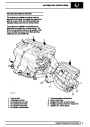
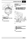
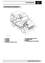
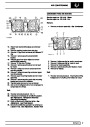
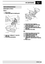
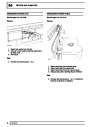
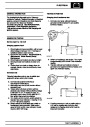
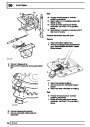
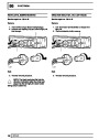
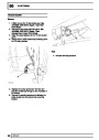
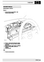
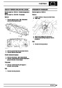
Remove engine mounting fixings on both sides
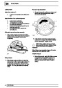
of cylinder block.
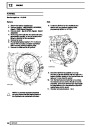
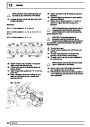
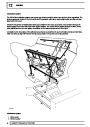
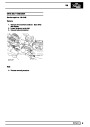
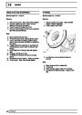
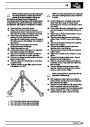
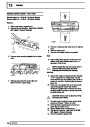
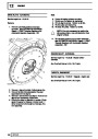
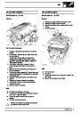
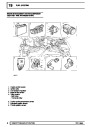
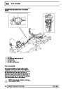
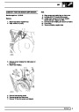
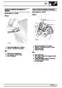
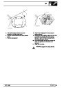
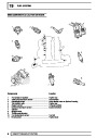
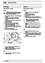
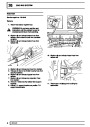
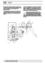
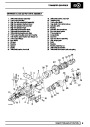
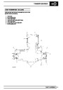
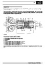
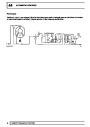
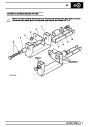
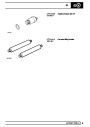
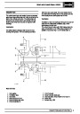
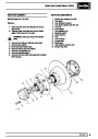
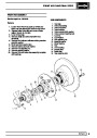
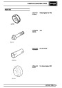
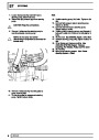
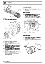
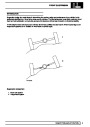
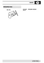
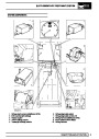
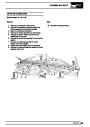
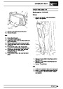
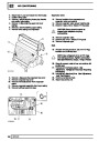
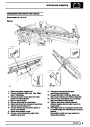
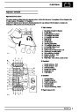
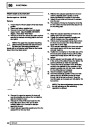
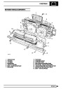
Fit lifting chains to engine lifting eyes as shown
in illustration RR1780E.
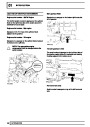
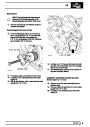
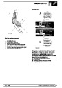
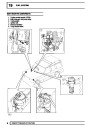
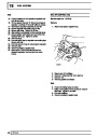
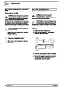
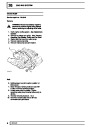
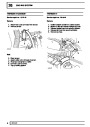
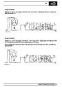
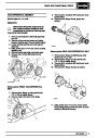
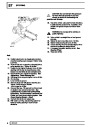
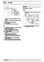
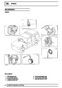
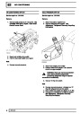
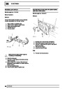
34. Remove nuts securing exhaust downpipes to
manifolds, remove heat shield from right hand
side downpipe.
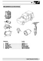
35. Remove electrical leads from starter motor
solenoid. Disconnect multi-plug from oil level
sensor on side of sump, if fitted.
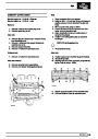
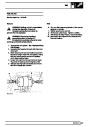
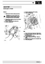
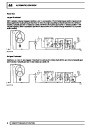
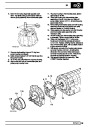
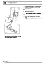
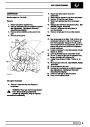
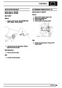
NOTE: Instructions 37, 38 and 39 refer to
automatic vehicles only.
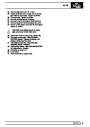
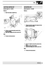
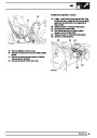
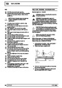
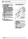
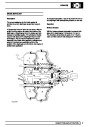
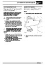
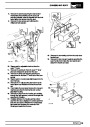
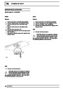
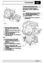
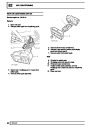
36.
37.
38.
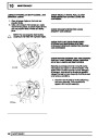
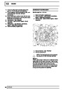
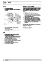
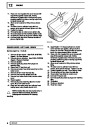
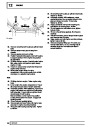
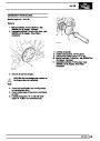
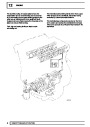
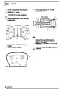
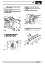
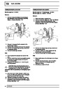
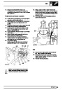
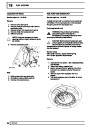
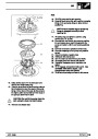
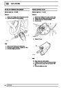
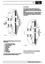
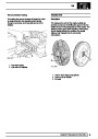
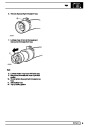
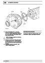
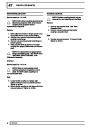
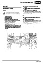
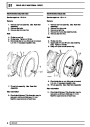
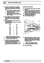
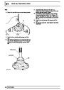
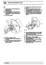
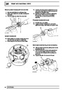
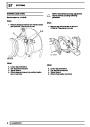
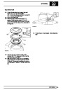
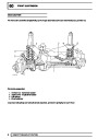
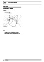
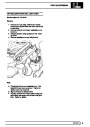
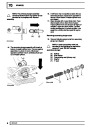
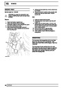
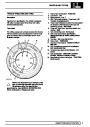
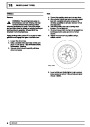
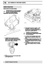
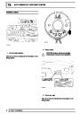
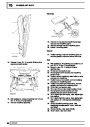
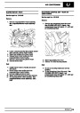
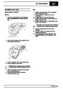
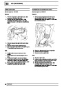
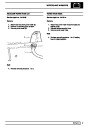
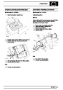
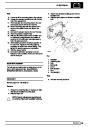
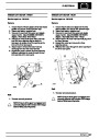
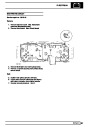
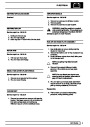
With assistance rotate engine at crankshaft
pulley until two access holes in drive plate/ring
gear assembly are visible.
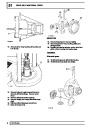
Remove two bolts visible through access holes.
Mark one access hole and one bolt hole to
ensure unit is reassembled in its original position
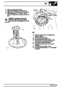
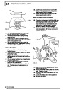
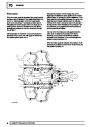
Rotate crankshaft 180˚ until two remaining
access holes are visible, remove two bolts.
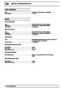
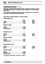
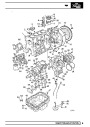
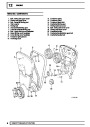
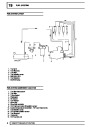
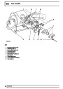
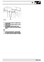
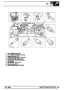
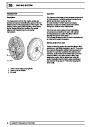
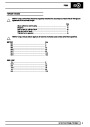
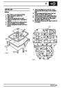
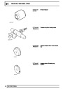
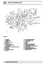
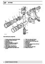
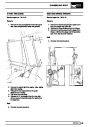
1.
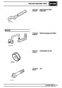
2.
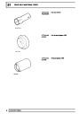
3.
L/H Front chain 356mm total overall length.
R/H Front chain 330mm total overall length.
R/H Rear chain 457mm total overall length.
REPAIR
13
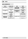
| Categories | Range Rover |
|---|---|
| Tags | Land Rover |
| Model Year | 1998 |
| Download File |
|
| Document Type | Workshop Manual |
| Language | English |
| Product Brand | Land Rover |
| Document File Type | |
| Publisher | landrover.com |
| Wikipedia's Page | http://en.wikipedia.org/wiki/Land_Rover |
| Copyright | Attribution Non-commercial |
(0 votes, average: 0 out of 5)