


70
BRAKES
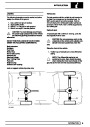
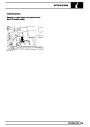
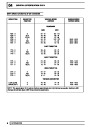
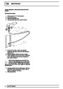
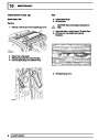
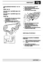
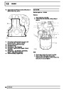
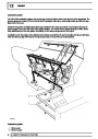
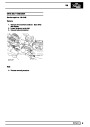
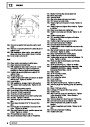
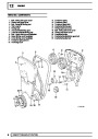
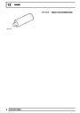
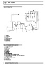
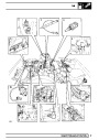
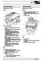
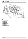
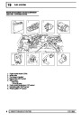
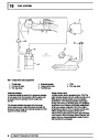
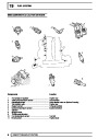
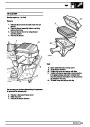
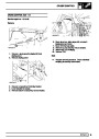
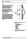
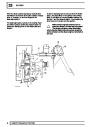
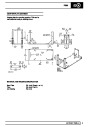
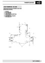
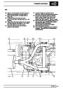
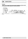
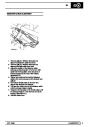
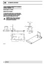
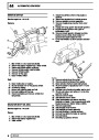
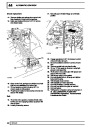
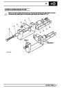
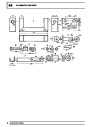
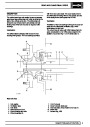
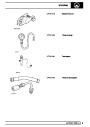
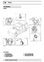
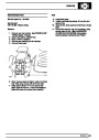
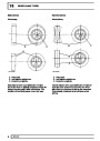
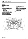
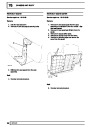
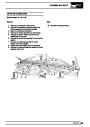
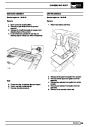
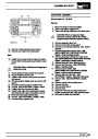
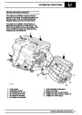
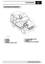
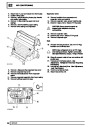
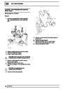
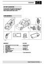
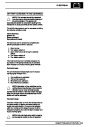
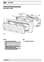
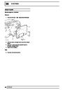
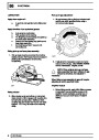
SENSORS - FRONT
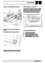
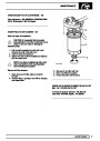
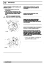
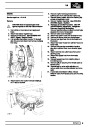
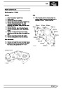
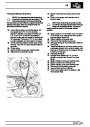
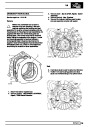
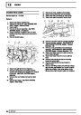
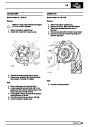
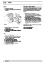
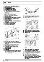
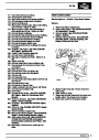
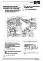
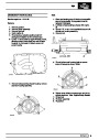
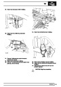
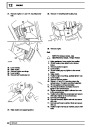
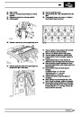
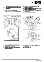
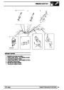
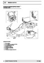
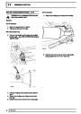
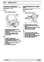
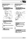
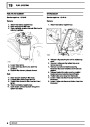
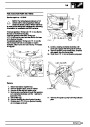
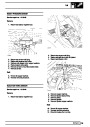
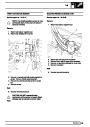
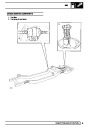
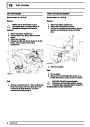
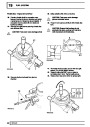
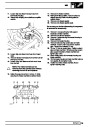
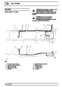
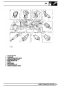
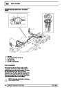
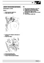
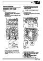
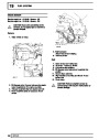
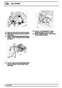
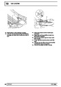
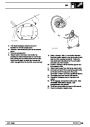
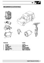
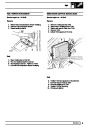
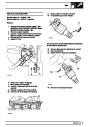
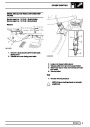
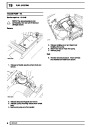
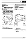
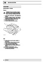
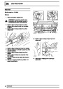
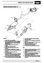
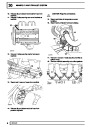
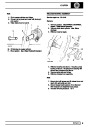
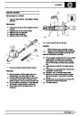
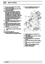
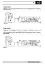
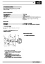
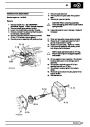
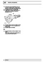
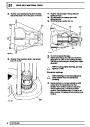
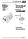
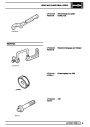
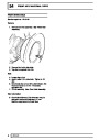
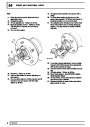
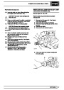
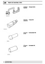
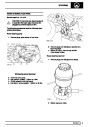
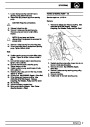
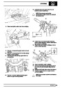
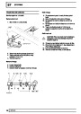
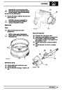
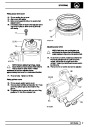
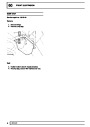
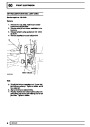
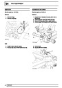
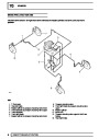
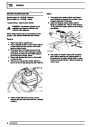
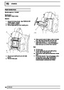
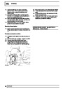
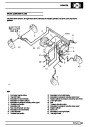
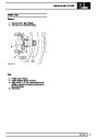
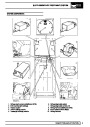
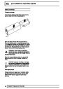
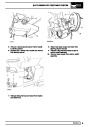
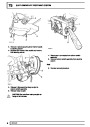
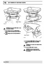
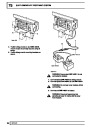
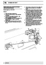
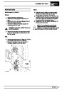
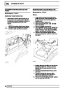
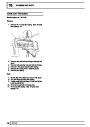
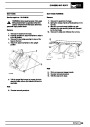
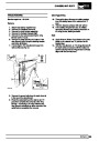
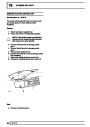
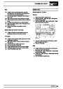
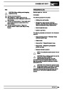
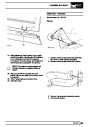
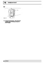
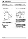
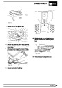
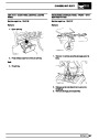
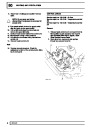
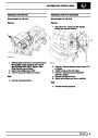
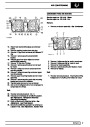
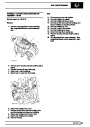
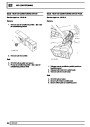
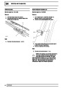
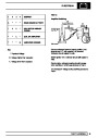
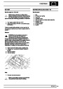
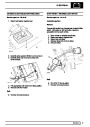
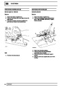
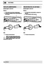
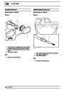
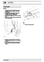
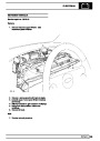
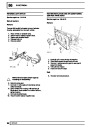
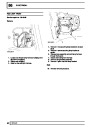
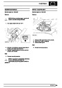
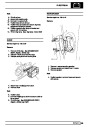
5. Release harness cable ties, remove sensor lead
from vehicle.
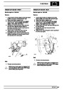
Service repair no - 70.65.32
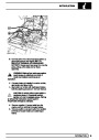
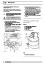
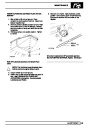
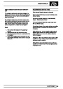
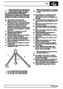
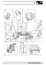
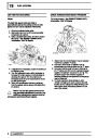
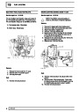
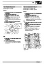
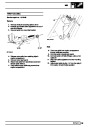
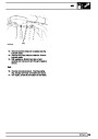
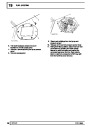
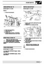
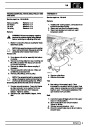
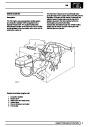
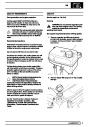
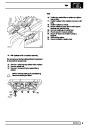
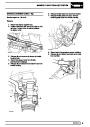
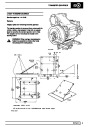
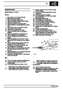
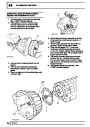
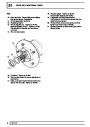
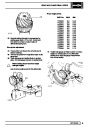
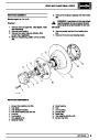
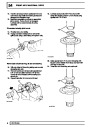
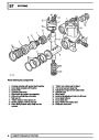
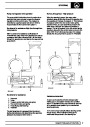
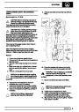
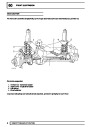
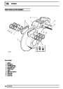
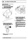
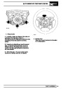
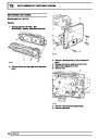
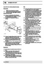
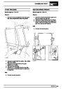
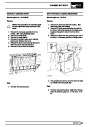
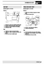
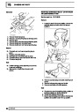
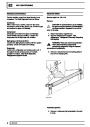
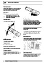
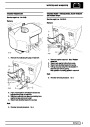
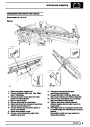
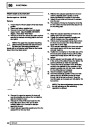
6. Remove top swivel retaining bolts complete with
brake jump hose and sensor seal. Remove
sensor bush.
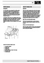
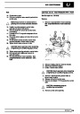
CAUTION: If a sensor is removed for any
reason, a NEW sensor bush and seal must
be fitted.
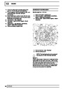
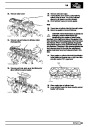
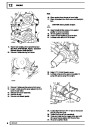
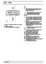
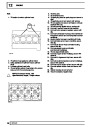
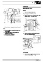
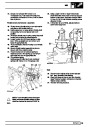
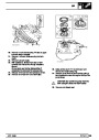
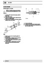
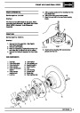
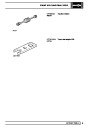
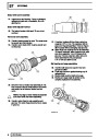
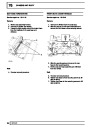
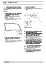
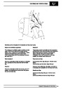
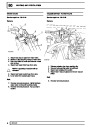
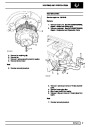
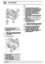
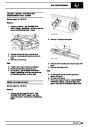
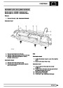
Refit
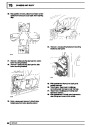
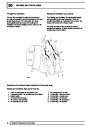
Remove
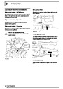
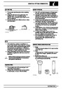
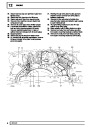
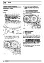
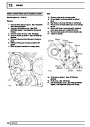
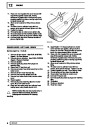
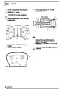
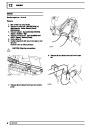
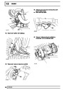
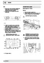
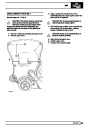
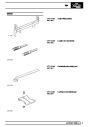
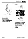
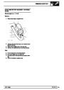
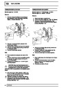
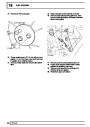
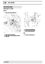
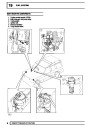
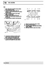
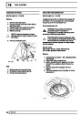
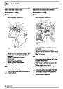
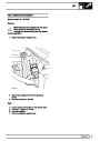
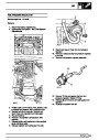
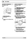
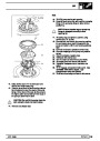
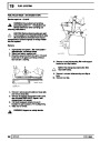
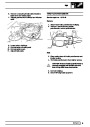
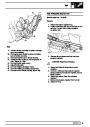
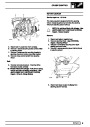
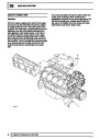
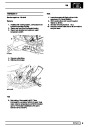
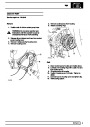
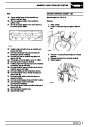
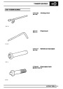
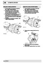
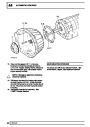
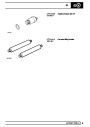
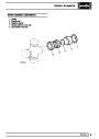
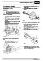
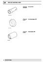
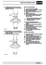
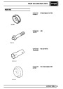
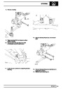
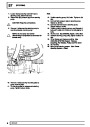
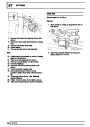
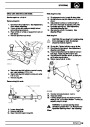
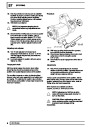
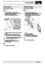
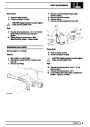
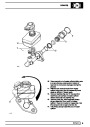
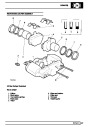
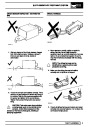
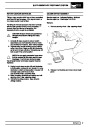
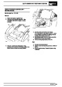
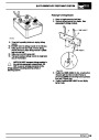
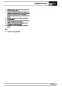
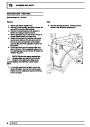
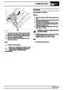
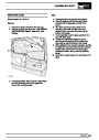
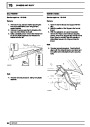
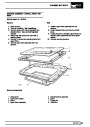
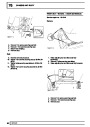
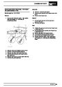
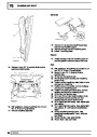
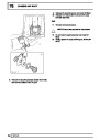
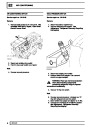
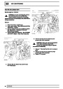
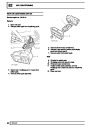
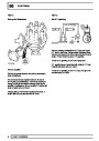
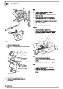
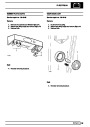
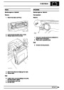
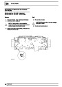
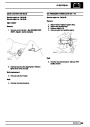
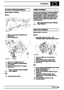
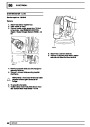
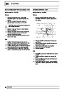
7. Insert new sensor bush and seal.
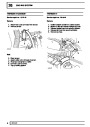
8.
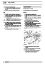
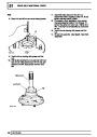
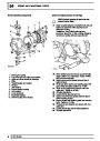
Refit brake jump hose bracket, coat bolts with
Loctite 270.
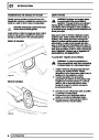
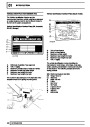
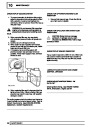
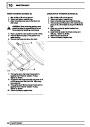
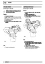
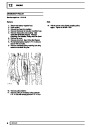
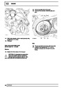
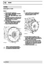
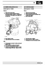
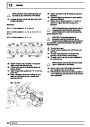
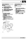
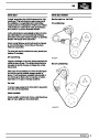
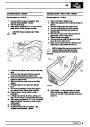
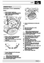
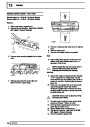
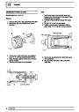
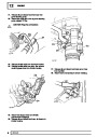
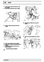
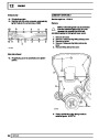
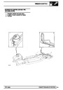
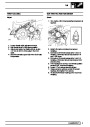
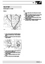
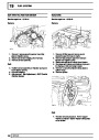
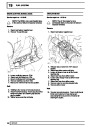
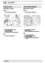
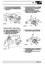
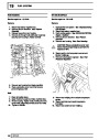
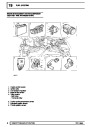
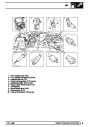
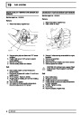
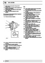
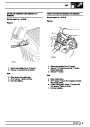
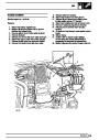
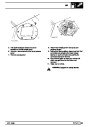
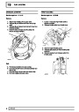
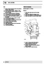
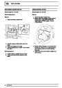
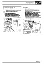
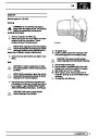
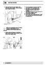
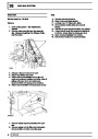
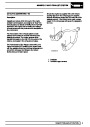
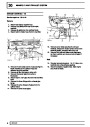
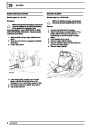
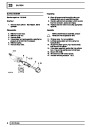
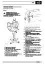
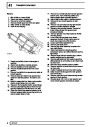
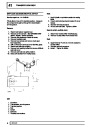
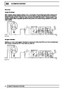
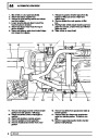
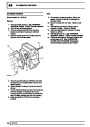
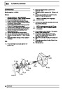
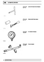
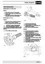
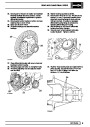
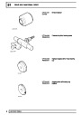
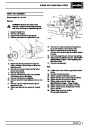
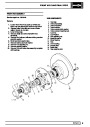
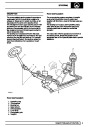
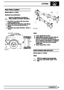
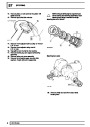
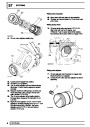
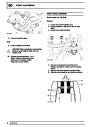
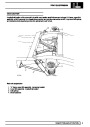
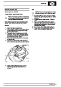
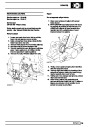
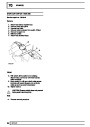
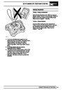
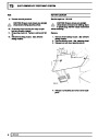
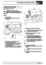
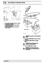
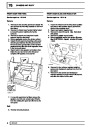
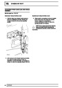
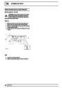
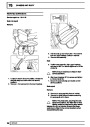
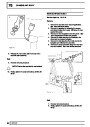
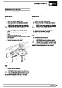
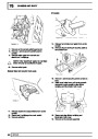
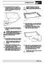
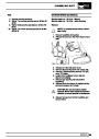
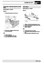
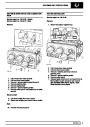
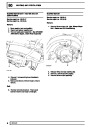
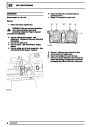
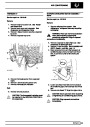
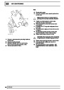
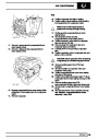
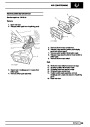
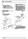
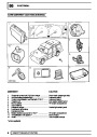
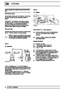
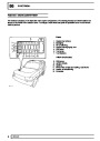
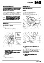
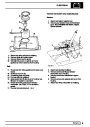
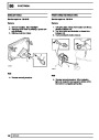
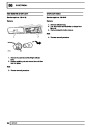
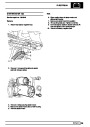
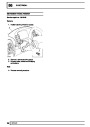
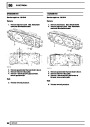
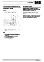
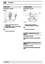
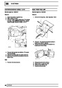
1.
2.
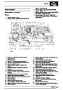
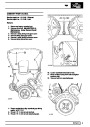
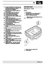
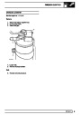
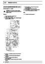
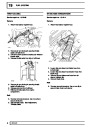
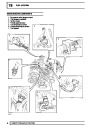
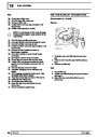
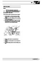
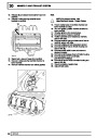
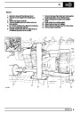
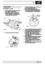
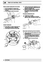
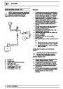
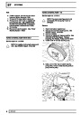
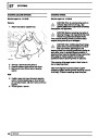
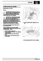
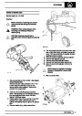
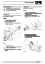
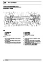
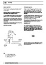
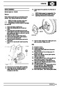
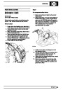
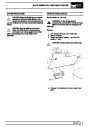
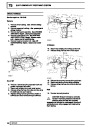
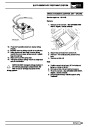
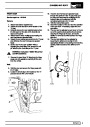
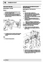
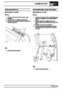
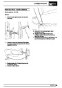
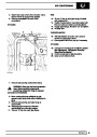
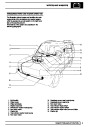
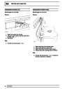
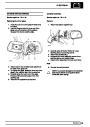
Disconnect battery negative lead.
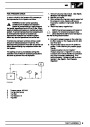
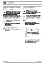
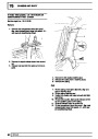
Disconnect required sensor electrical
connection, located on inner wing [fender] panel.
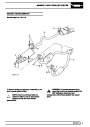
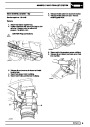
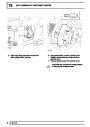
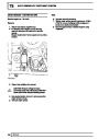
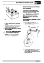
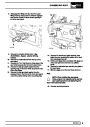
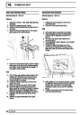
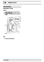
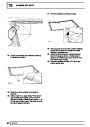
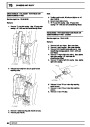
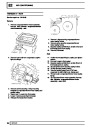
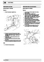
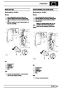
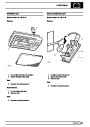
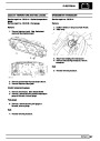
Remove sensor lead from clips.
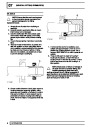
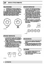
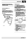
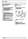
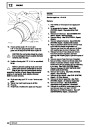
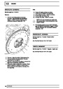
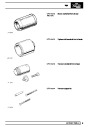
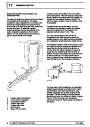
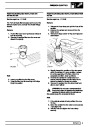
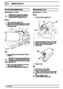
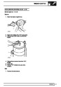
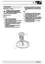
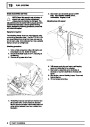
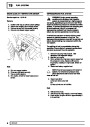
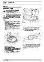
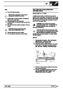
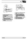
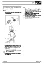
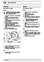
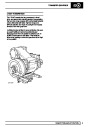
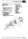
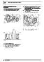
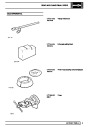
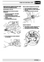
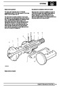
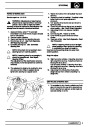
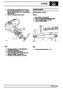
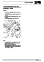
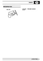
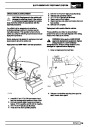
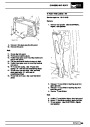
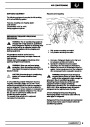
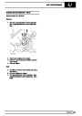
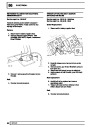
Clean area surrounding sensor to prevent
ingress of dirt. Using a suitable lever pry sensor
from mounting bush.
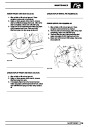
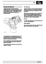
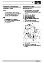
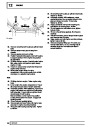
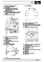
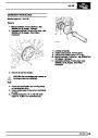
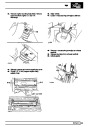
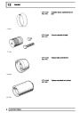
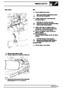
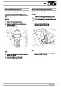
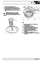
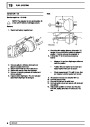
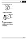
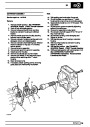
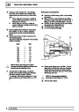
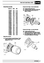
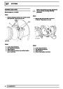
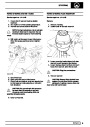
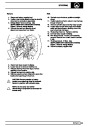
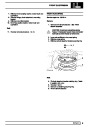
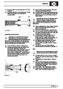
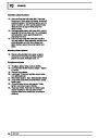
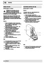
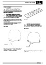
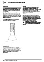
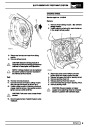
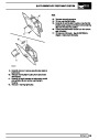
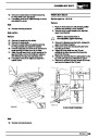
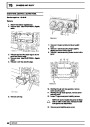
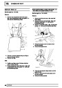
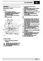
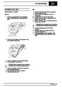
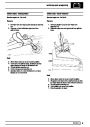
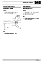
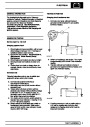
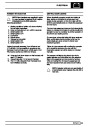
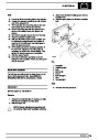
9. Lightly coat new sensor using EP 90 oil. Push
sensor through bush until it contacts exciter ring.
Sensor will be ’knocked back’ to correct position
when vehicle is driven.
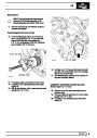
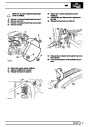
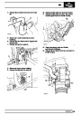
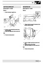
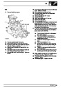
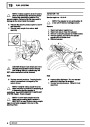
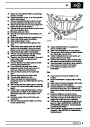
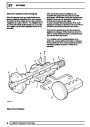
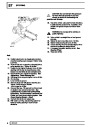
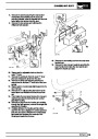
10. Secure sensor lead in original position.
11. Reconnect sensor electrical connection.
3.
4.
12.
Drive vehicle to ensure ABS warning light is
extinguished.
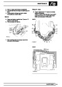
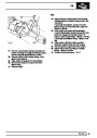
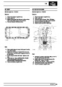
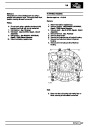
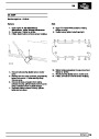
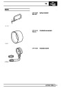
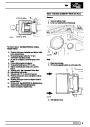
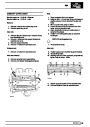
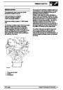
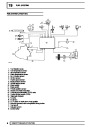
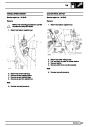
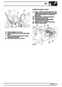
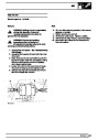
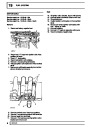
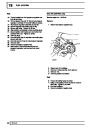
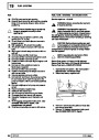
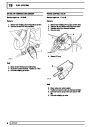
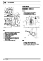
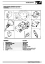
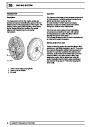
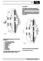
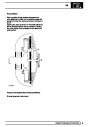
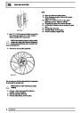
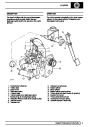
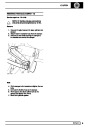
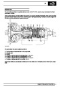
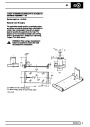
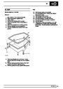
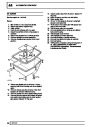
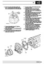
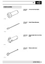
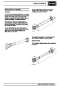
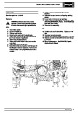
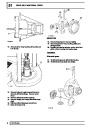
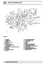
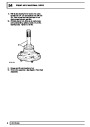
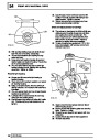
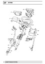
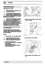
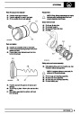
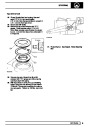
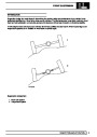
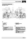
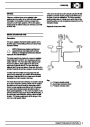
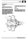
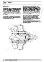
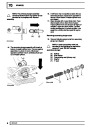
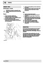
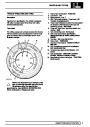
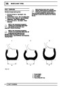
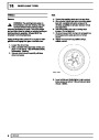
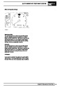
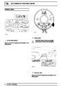
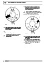
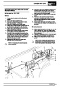
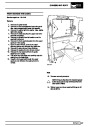
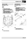
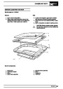
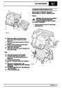
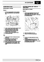
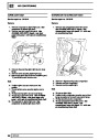
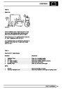
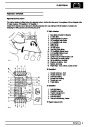
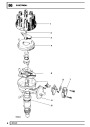
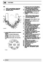
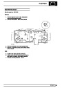
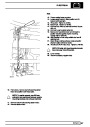
SENSOR RINGS
The rear sensor ring is assembled to the rear brake
disc to form part of the rear hub assembly. See
REAR AXLE AND FINAL DRIVE, Repair, Rear Hub
Assembly
The front sensor ring is a toothed ring on the axle
shaft which forms part of the front stub axle assembly.
See FRONT AXLE AND FINAL DRIVE, Overhaul,
Front Stub Axle, Constant Velocity Joint and
Swivel Pin Housing ABS
18
REPAIR
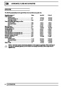
| Categories | Range Rover |
|---|---|
| Tags | Land Rover |
| Model Year | 1998 |
| Download File |
|
| Document Type | Workshop Manual |
| Language | English |
| Product Brand | Land Rover |
| Document File Type | |
| Publisher | landrover.com |
| Wikipedia's Page | http://en.wikipedia.org/wiki/Land_Rover |
| Copyright | Attribution Non-commercial |
(0 votes, average: 0 out of 5)