
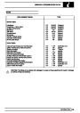
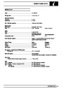


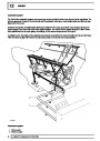


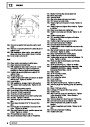
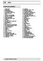
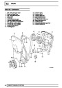
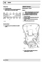
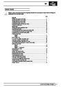


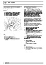
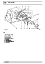
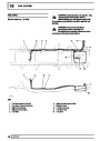
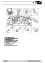
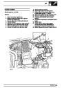
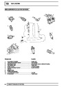


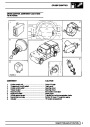
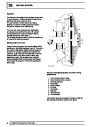


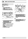

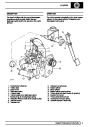
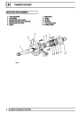
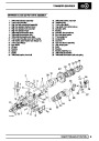
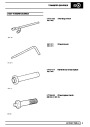
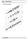
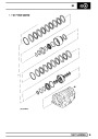
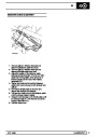
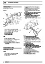
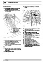
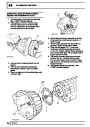
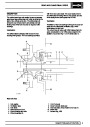
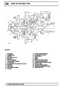

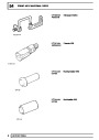
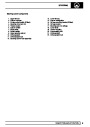
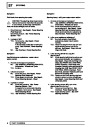

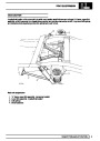

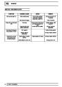

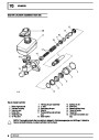
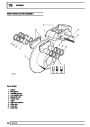
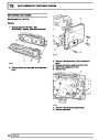
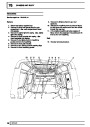

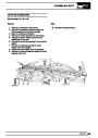
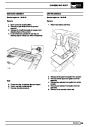
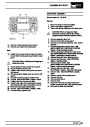
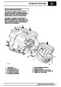

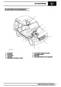

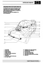
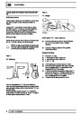
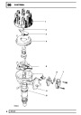
REAR AXLE AND FINAL DRIVE
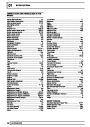
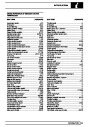
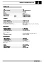
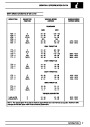
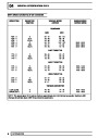
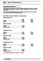
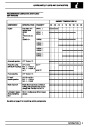
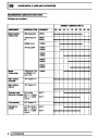
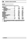
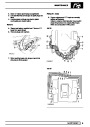
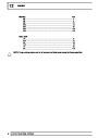
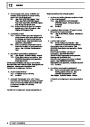
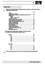
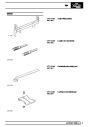
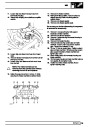
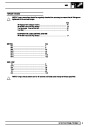
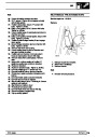
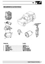
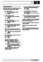
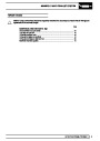
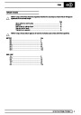
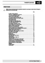
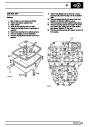
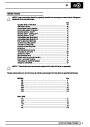
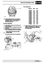
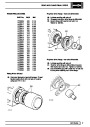
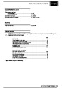
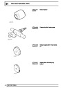
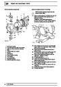
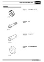
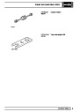
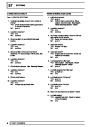
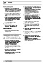
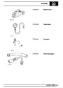
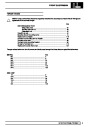
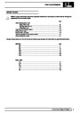
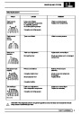
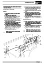
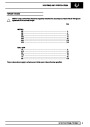
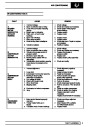
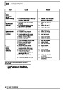
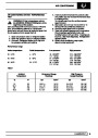
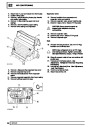
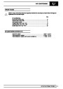
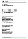
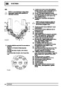
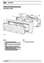
Pinion height shims
PART No.
INCH
MM
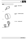
FTC3853
FTC3854
FTC3855
FTC3856
FTC3857
FTC3858
FTC3859
FTC3860
FTC3861
FTC3862
FTC3863
FTC3864
FTC3865
FTC3866
FTC3867
FTC3868
.061
.060
.059
.058
.057
.056
.055
.054
.053
.052
.051
.050
.049
.048
.047
.046
1.548
1.523
1.498
1.473
1.448
1.423
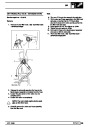
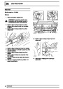
1.398
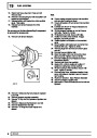
1.373
1.348
1.323
1.298
1.273
1.248
1.223
1.198
1.173
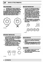
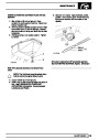
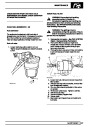
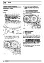
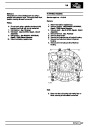
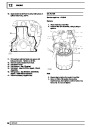
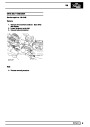
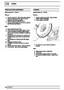
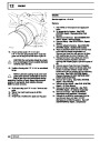
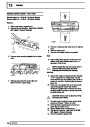
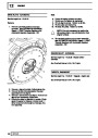
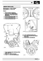
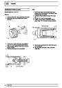
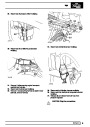
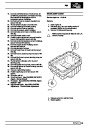
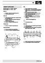
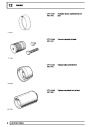
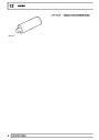
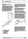
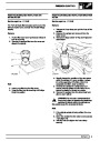
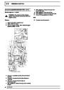
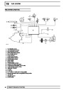
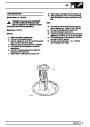
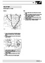
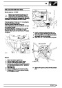
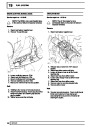
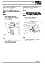
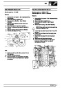
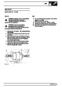
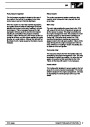
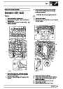
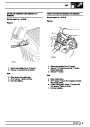
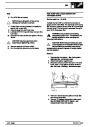
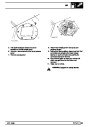
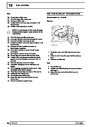
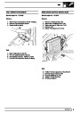
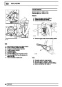
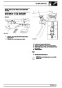
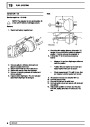
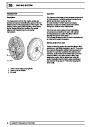
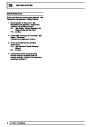
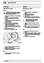
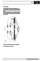
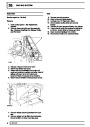
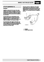
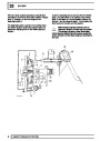
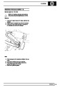
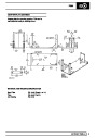
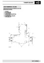
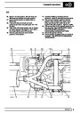
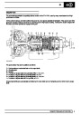
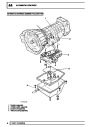
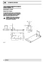
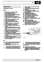
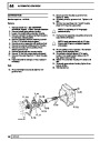
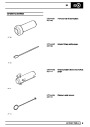
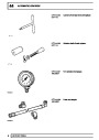
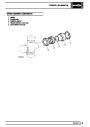
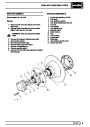
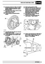
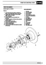
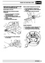
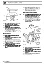
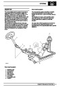
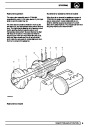
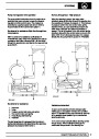
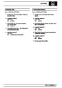
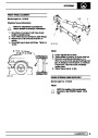
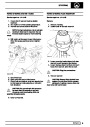
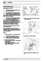
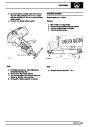
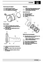
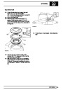
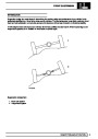
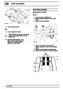
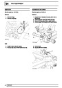
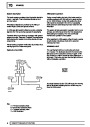
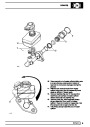
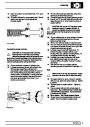
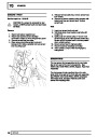
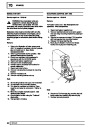
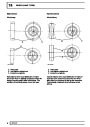
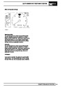
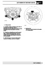
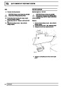
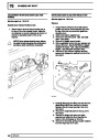
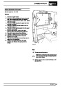
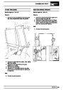
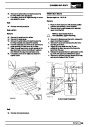
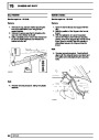
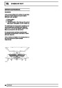
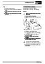
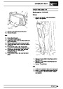
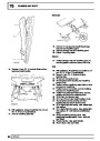
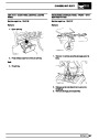
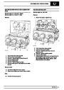
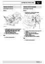
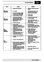
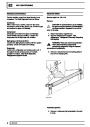
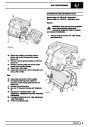
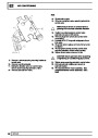
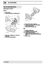
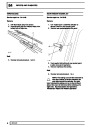
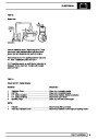
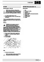
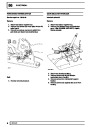
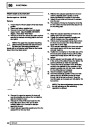
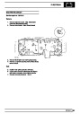
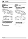
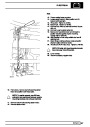
43.
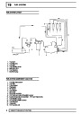
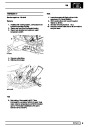
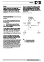
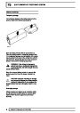
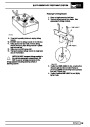
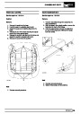
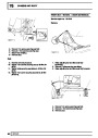
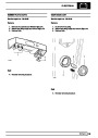
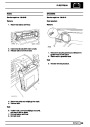
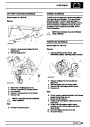
Nominal setting dimension is represented by
setting gauge block LRT-54-503. Referenced
from pinion end face to bottom radius of
differential bearing bore.
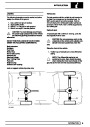
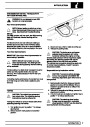
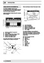
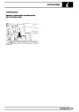
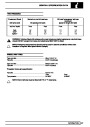
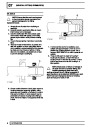
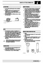
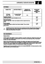
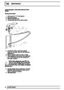
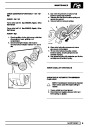
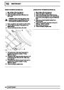
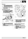
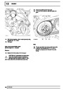
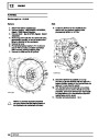
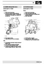
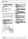
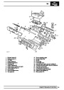
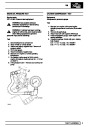
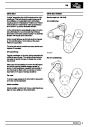
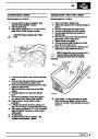
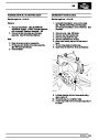
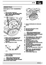
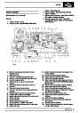
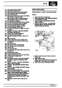
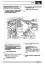
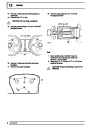
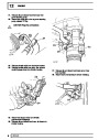
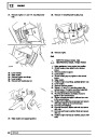
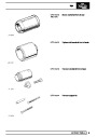
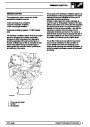
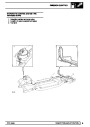
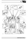
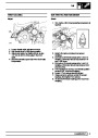
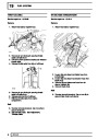
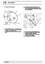
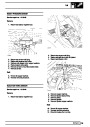
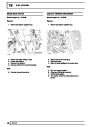
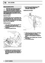
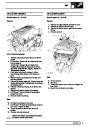
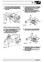
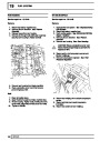
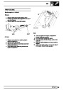
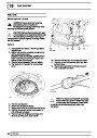
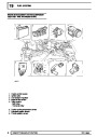
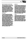
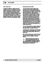
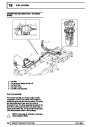
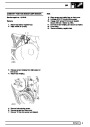
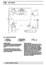
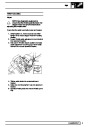
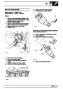
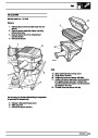
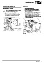
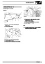
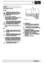
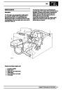
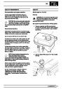
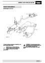
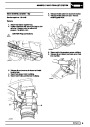
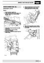
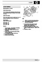
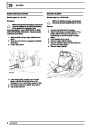
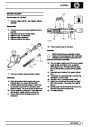
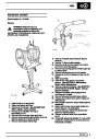
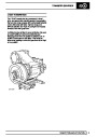
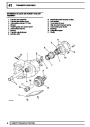
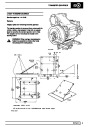
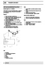
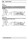
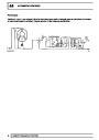
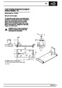
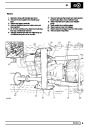
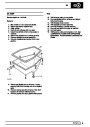
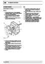
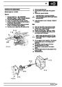
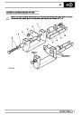
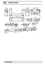
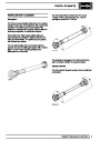
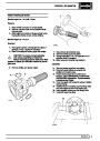
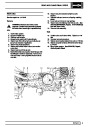
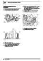
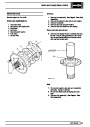
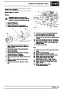
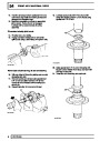
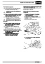
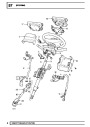
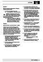
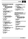
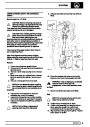
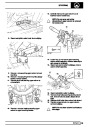
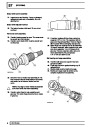
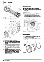
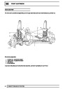
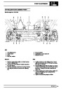
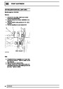
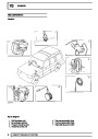
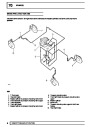
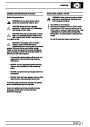
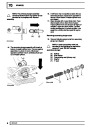
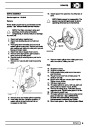
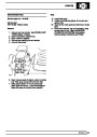
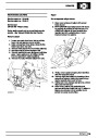
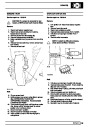
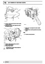
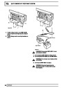
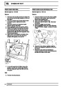
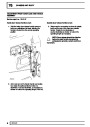
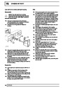
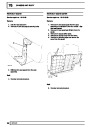
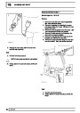
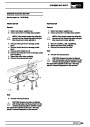
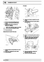
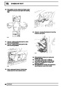
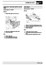
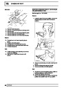
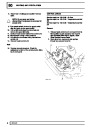
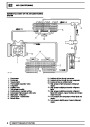
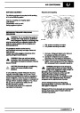
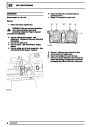
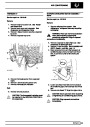
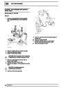
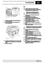
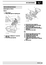
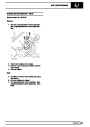
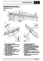
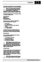
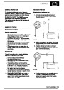
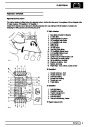
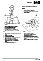
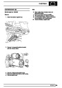
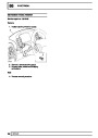
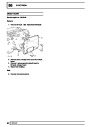
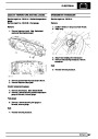
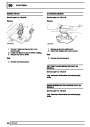
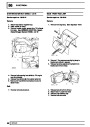
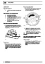
Drive pinion adjustment
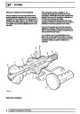
44.
45.
46.
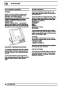
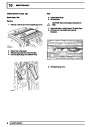
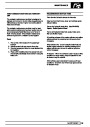
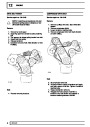
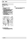
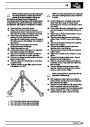
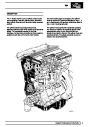
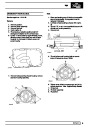
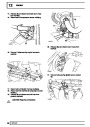
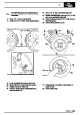
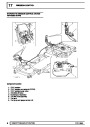
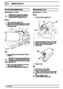
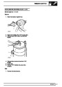
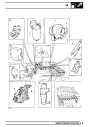
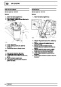
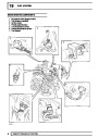
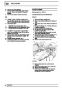
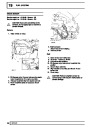
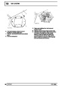
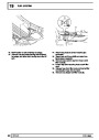
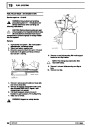
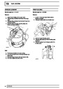
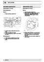
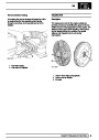
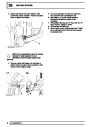
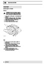
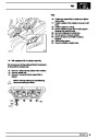
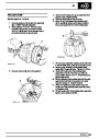
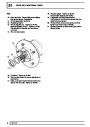
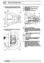
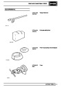
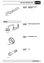
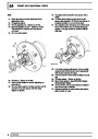
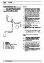
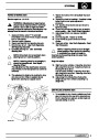
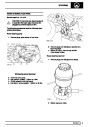
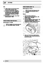
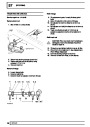
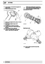
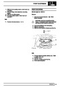
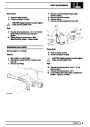
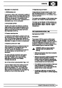
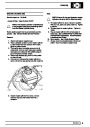
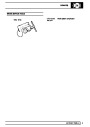
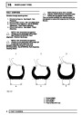
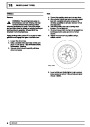
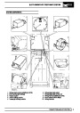
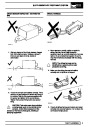
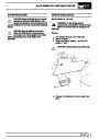
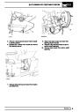
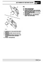
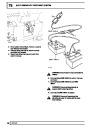
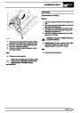
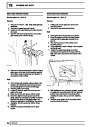
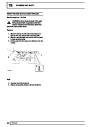
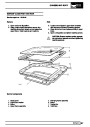
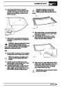
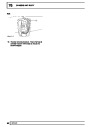
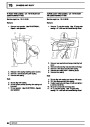
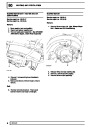
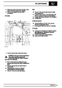
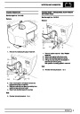
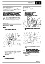
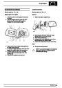
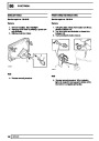
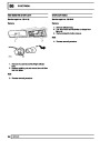
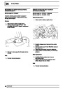
Ensure pinion end face is free of burrs around
etched markings.
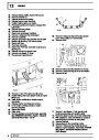
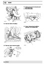
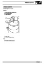
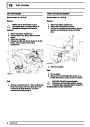
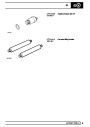
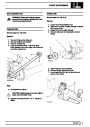
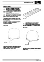
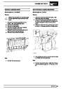
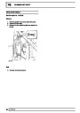
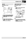
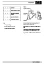
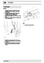
Remove keep disc from magnetized base of dial
gauge tool.
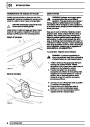
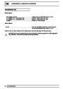
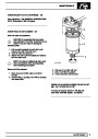
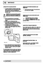
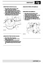
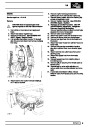
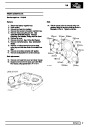
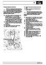
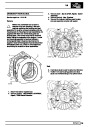
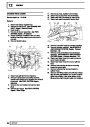
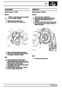
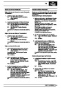
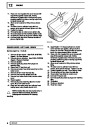
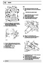
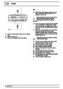
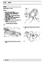
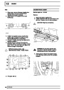
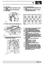
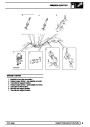
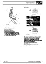
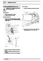
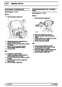
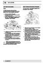
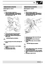
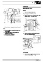
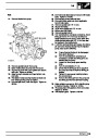
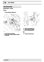
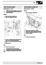
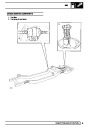
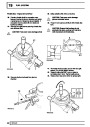
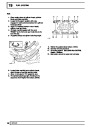
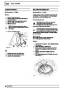
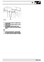
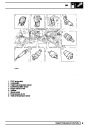
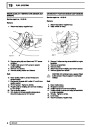
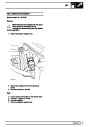
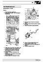
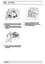
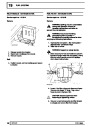
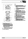
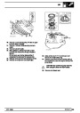
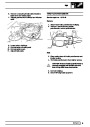
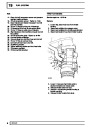
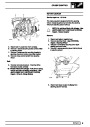
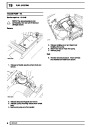
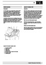
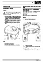
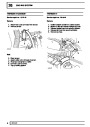
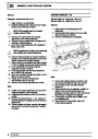
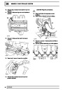
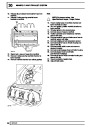
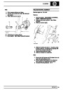
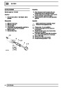
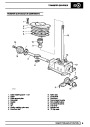
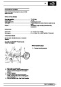
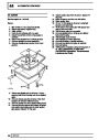
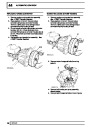
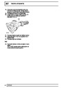
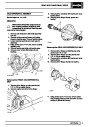
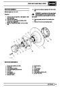
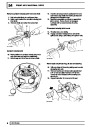
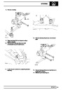
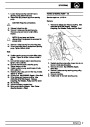
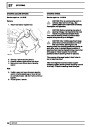
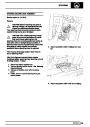
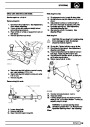
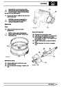
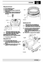
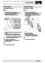
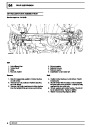
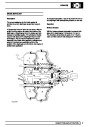
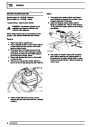
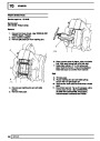
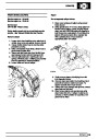
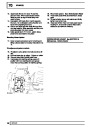
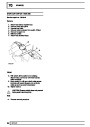
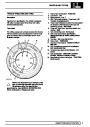
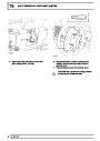
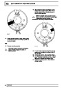
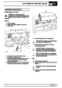
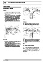
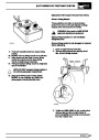
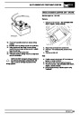
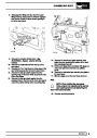
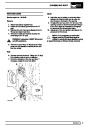
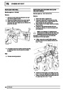
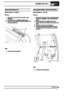
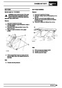
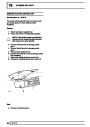
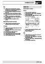
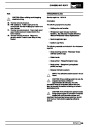
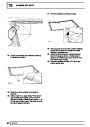
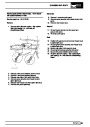
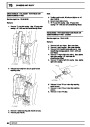
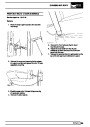
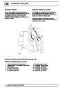
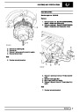
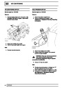
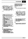
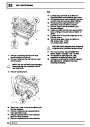
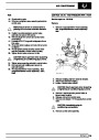
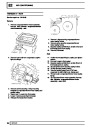
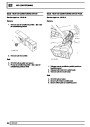
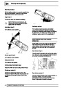
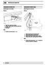
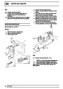
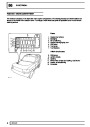
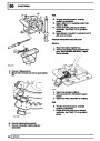
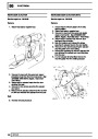
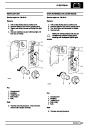
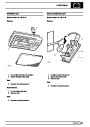
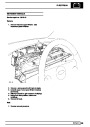
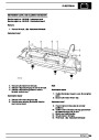
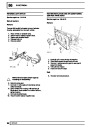
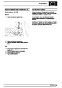
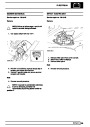
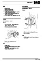
Place dial gauge and setting block on surface
plate. Zero dial gauge trace pin on setting block.
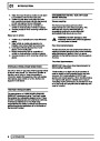
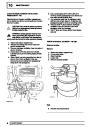
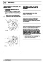
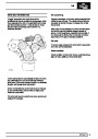
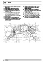
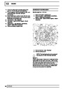
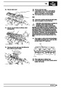
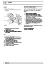
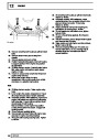
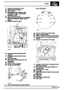
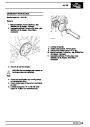
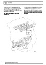
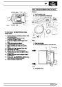
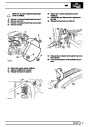
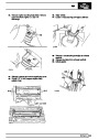
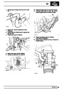
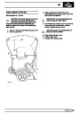
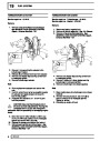
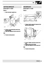
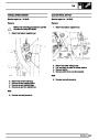
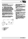
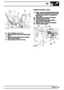
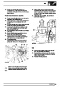
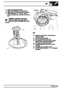
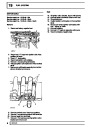
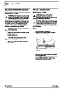
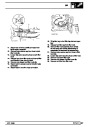
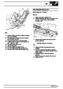
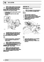
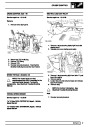
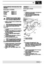
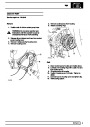
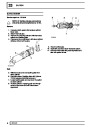
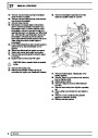
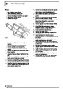
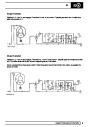
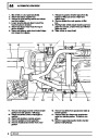
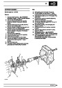
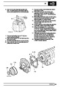
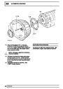
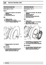
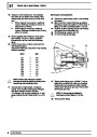
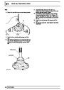
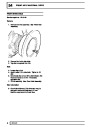
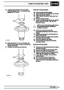
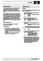
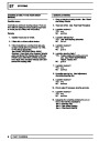
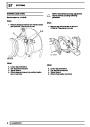
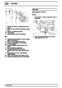
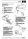
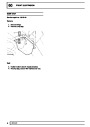
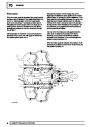
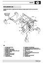
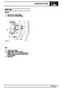
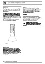
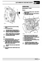
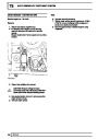
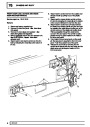
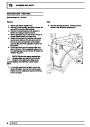
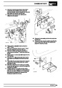
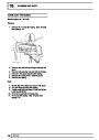
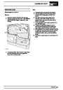
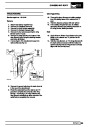
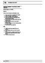
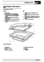
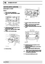
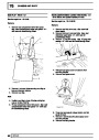
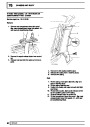
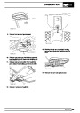
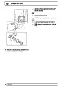
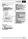
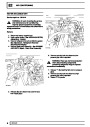
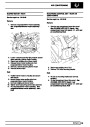
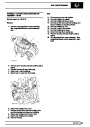
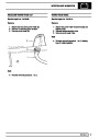
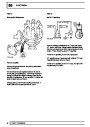
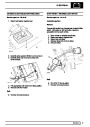
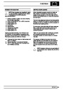
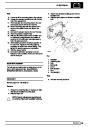
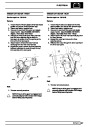
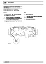
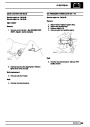
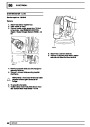
47.
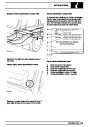
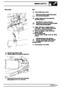
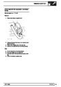
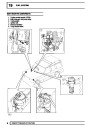
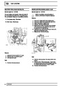
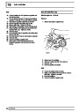
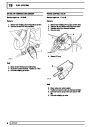
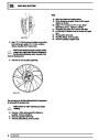
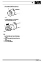
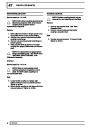
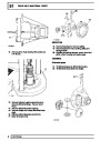
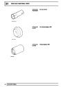
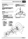
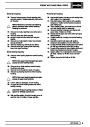
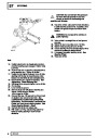
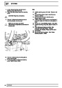
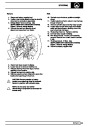
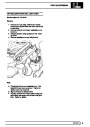
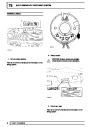
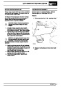
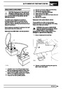
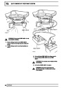
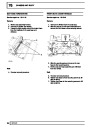
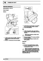
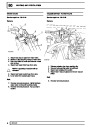
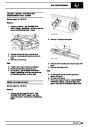
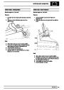
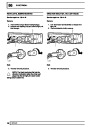
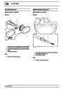
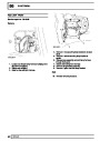
Position dial gauge centrally on pinion end face,
register on lowest point on one differential
bearing bore. Note dial gauge measurement
from zeroed setting.
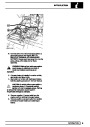
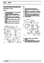
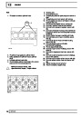
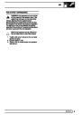
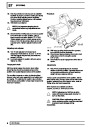
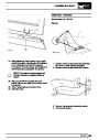
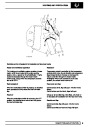
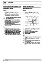
NOTE: Setting block has three height
settings heights.
Use 39.50mm setting mark for this differential.
OVERHAUL
5
| Categories | Range Rover |
|---|---|
| Tags | Land Rover |
| Model Year | 1998 |
| Download File |
|
| Document Type | Workshop Manual |
| Language | English |
| Product Brand | Land Rover |
| Document File Type | |
| Publisher | landrover.com |
| Wikipedia's Page | http://en.wikipedia.org/wiki/Land_Rover |
| Copyright | Attribution Non-commercial |
(0 votes, average: 0 out of 5)