


19
FUEL SYSTEM
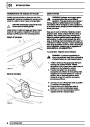
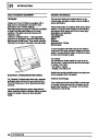
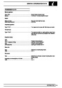
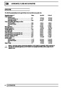
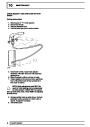
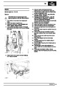
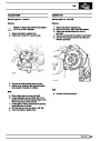
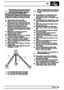
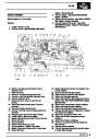
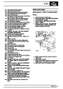
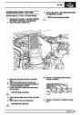
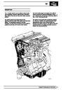
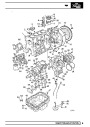
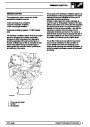
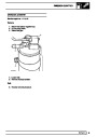
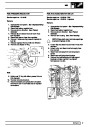
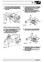
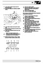
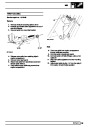
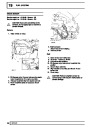
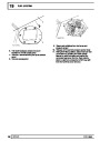
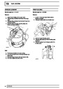
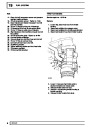
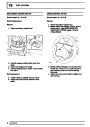
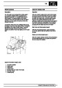
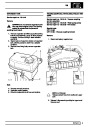
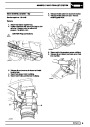
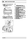
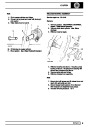
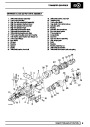
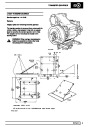
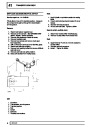
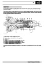
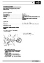
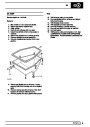
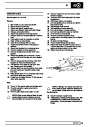
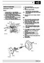
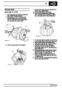
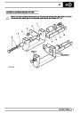
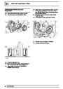
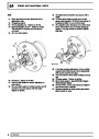
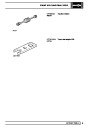
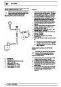
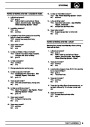
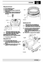
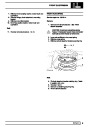
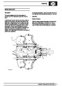
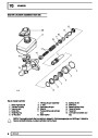
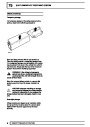
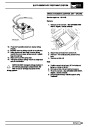
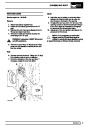
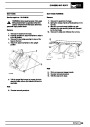
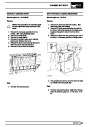
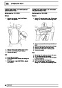
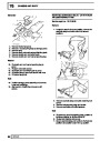
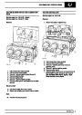
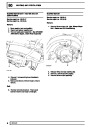
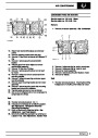
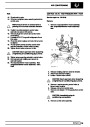
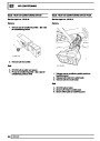
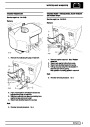
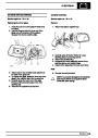
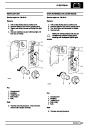
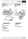
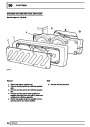
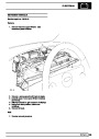
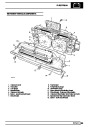
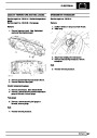
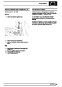
DESCRIPTION ELECTRONIC DIESEL CONTROL
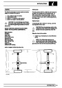
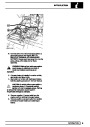
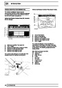
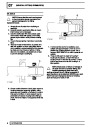
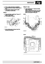
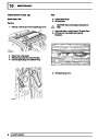
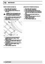
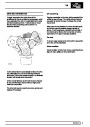
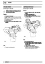
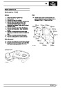
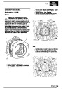
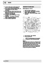
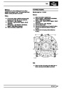
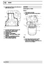
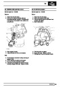
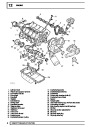
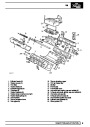
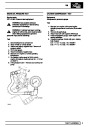
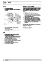
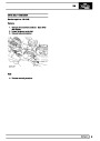
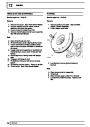
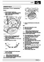
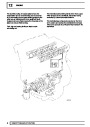
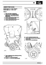
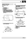
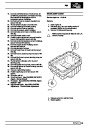
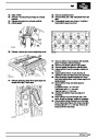
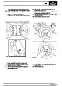
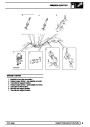
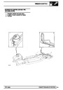
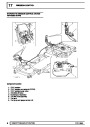
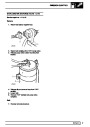
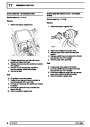
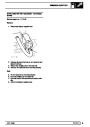
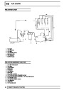
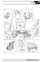
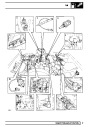
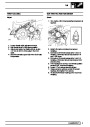
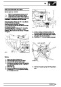
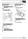
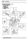
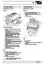
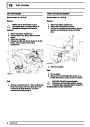
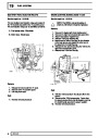
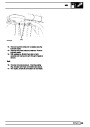
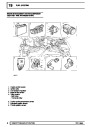
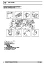
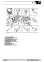
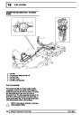
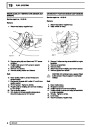
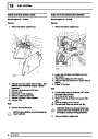
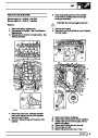
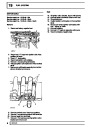
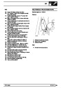
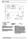
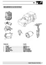
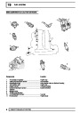
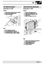
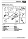
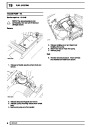
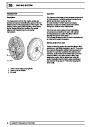
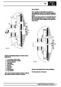
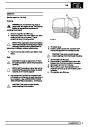
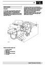
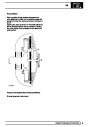
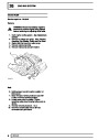
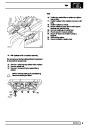
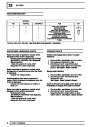
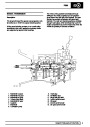
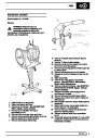
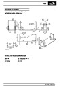
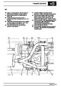
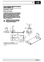
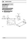
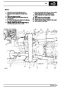
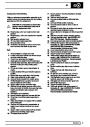
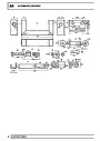
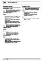
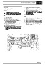
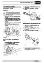
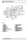
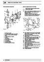
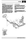
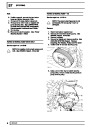
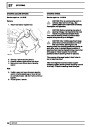
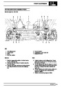
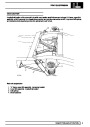
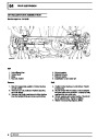
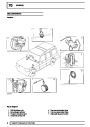
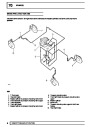
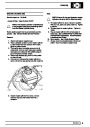
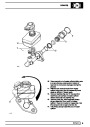
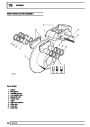
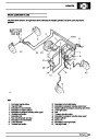
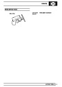
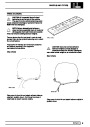
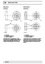
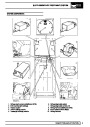
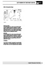
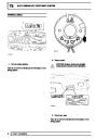
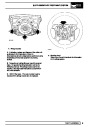
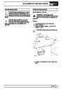
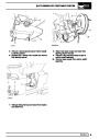
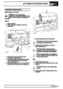
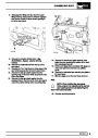
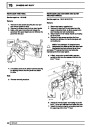
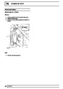
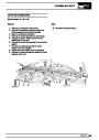
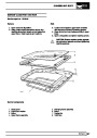
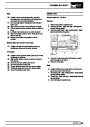
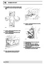
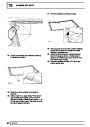
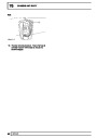
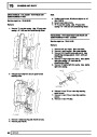
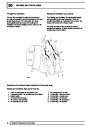
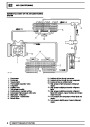
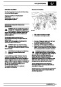
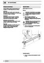
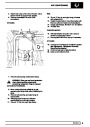
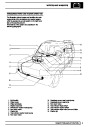
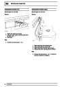
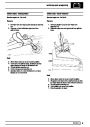
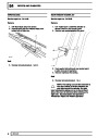
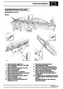
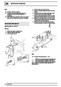
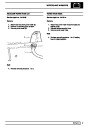
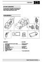
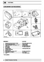
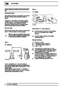
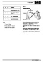
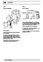
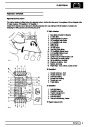
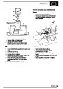
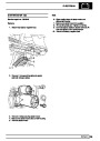
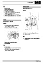
FUEL SYSTEM COMPONENT LOCATION EDC
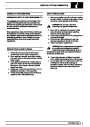
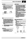
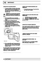
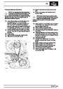
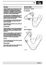
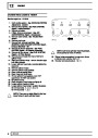
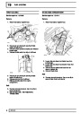
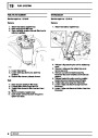
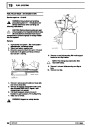
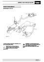
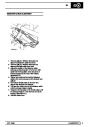
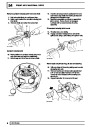
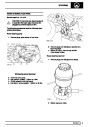
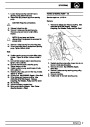
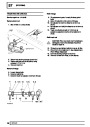
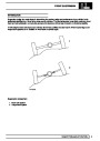
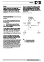
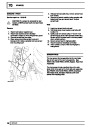
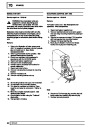
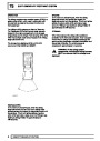
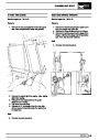
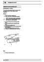
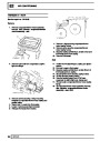
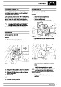
The Electronic Diesel Control (EDC) ’drive by wire’
system derives its from the replacement of
conventional mechanical controls by electronic
components.
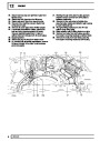
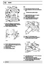
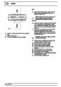
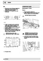
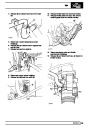
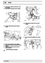
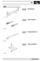
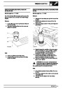
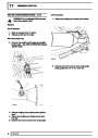
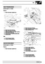
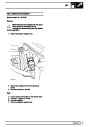
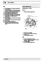
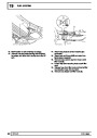
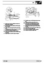
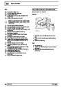
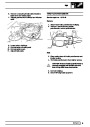
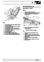
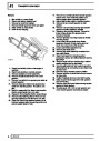
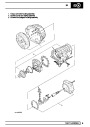
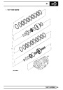
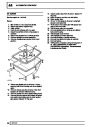
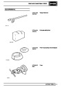
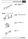
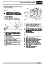
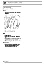
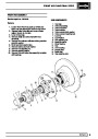
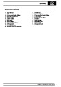
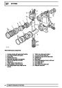
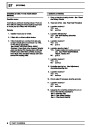
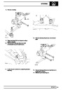
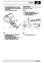
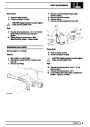
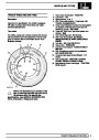
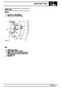
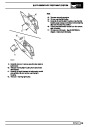
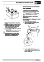
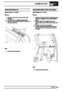
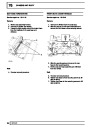
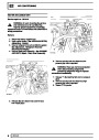
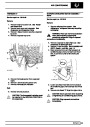
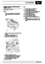
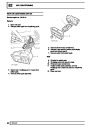
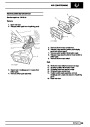
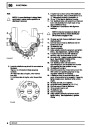
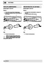
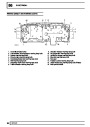
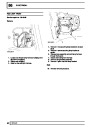
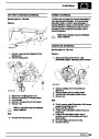
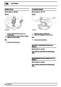
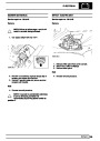
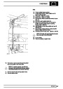
1. Vehicle speed sensor
2. No. 4 injector sensor
3. Coolant temperature sensor
4. Boost pressure sensor
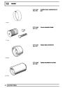
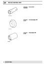
5.
Electro-pneumatic modulator
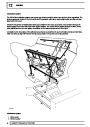
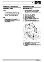
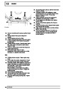
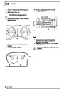
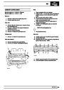
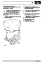
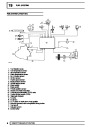
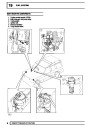
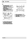
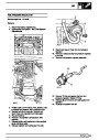
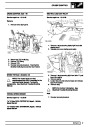
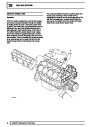
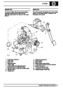
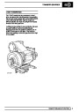
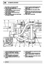
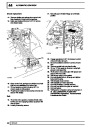
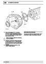
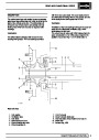
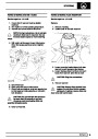
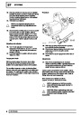
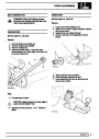
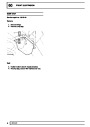
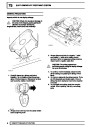
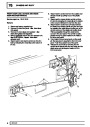
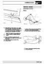
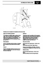
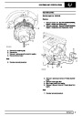
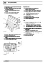
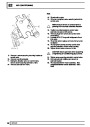
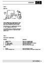
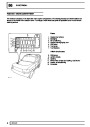
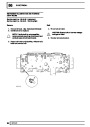
The EDC system supplies the exact amount of fuel to
the engine according to the prevailing engine
operating conditions. To monitor these conditions,
sensors are fitted to the engine to measure engine
parameters. Data from the sensors is received by the
Engine Control Module (ECM) which determines the
exact amount of fuel, injection timing and Exhaust
Gas Recirculation (EGR) required for any running
condition.
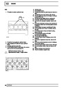
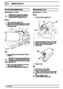
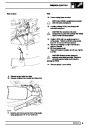
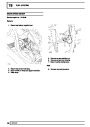
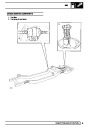
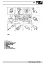
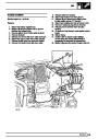
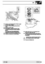
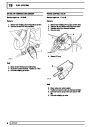
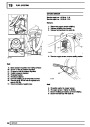
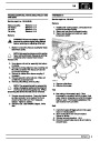
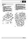
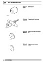
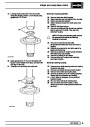
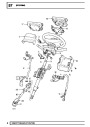
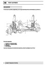
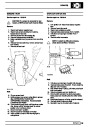
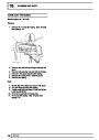
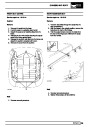
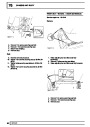
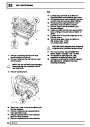
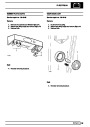
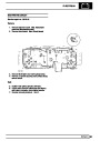
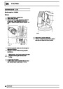
6. Airflow sensor
7. Engine speed sensor
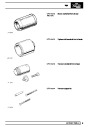
8. Brake/clutch switches
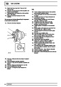
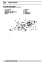
9. Injector pump
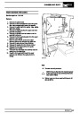
10. Throttle position sensor
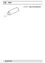
11. Engine control module
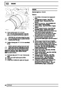
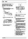
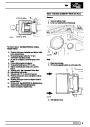
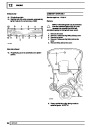
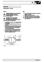
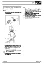
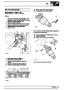
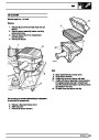
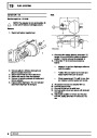
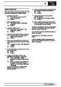
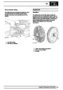
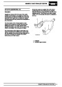
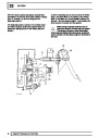
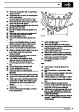
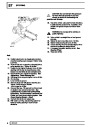
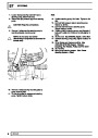
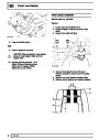
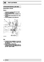
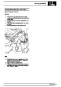
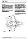
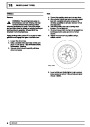
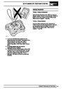
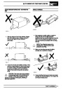
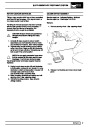
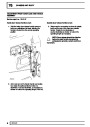
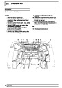
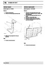
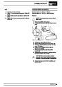
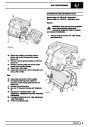
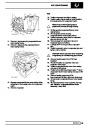
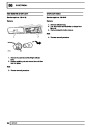
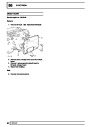
Safety and emergency features are built into the
system which protect the engine against overspeed
and overheating damage. In the event of component
failure the system is designed to compensate and
allow emergency start and limp home facilities to
operate. The ECM does this by substituting a default
value for the failed component which may result in a
noticeable loss in power but keeps the engine
running.
6
DESCRIPTION AND OPERATION
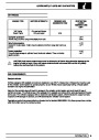
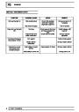
| Categories | Range Rover |
|---|---|
| Tags | Land Rover |
| Model Year | 1998 |
| Download File |
|
| Document Type | Workshop Manual |
| Language | English |
| Product Brand | Land Rover |
| Document File Type | |
| Publisher | landrover.com |
| Wikipedia's Page | http://en.wikipedia.org/wiki/Land_Rover |
| Copyright | Attribution Non-commercial |
(0 votes, average: 0 out of 5)