


75
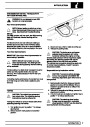
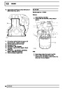
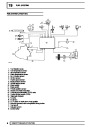
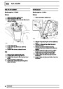
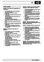
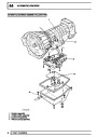
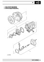
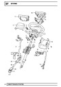
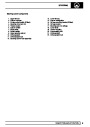
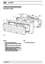
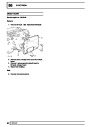
SUPPLEMENTARY RESTRAINT SYSTEM
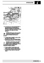
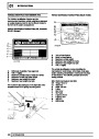
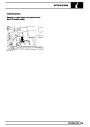
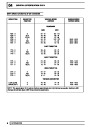
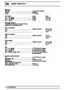
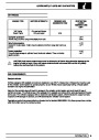
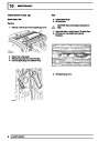
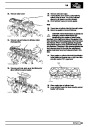
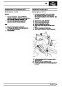
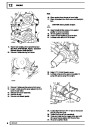
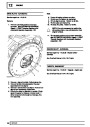
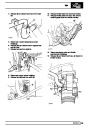
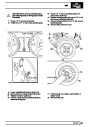
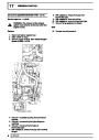
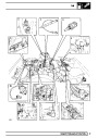
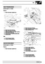
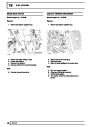
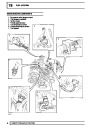
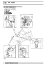
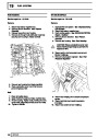
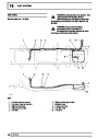
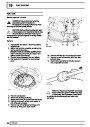
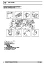
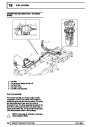
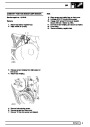
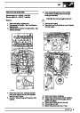
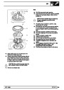
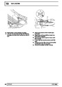
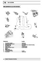
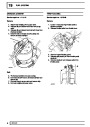
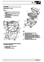
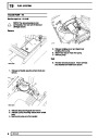
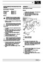
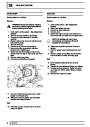
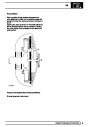
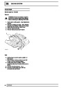
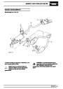
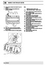
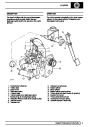
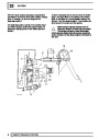
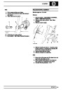
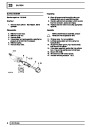
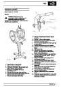
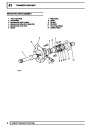
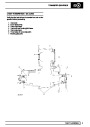
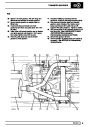
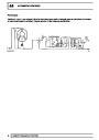
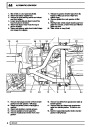
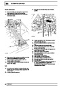
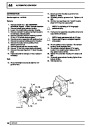
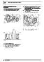
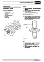
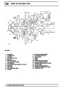
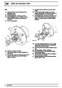
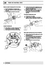
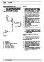
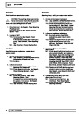
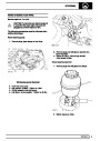
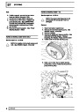
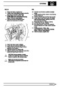
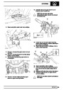
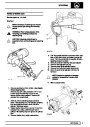
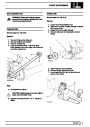
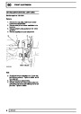
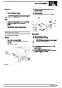
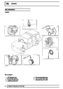
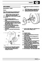
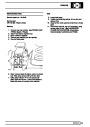
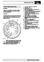
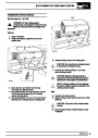
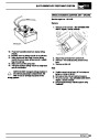
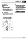
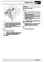
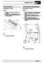
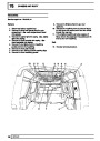
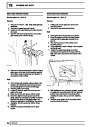
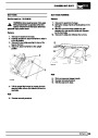
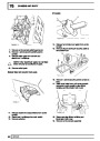
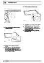
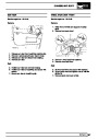
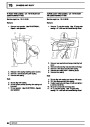
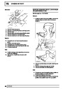
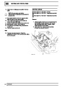
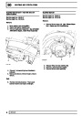
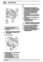
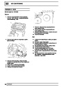
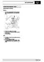
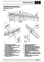
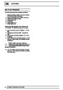
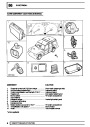
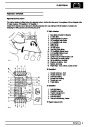
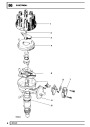
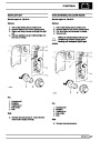
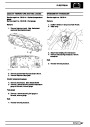
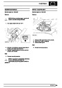
13.
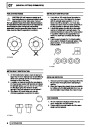
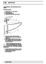
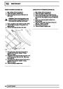
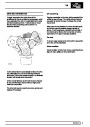
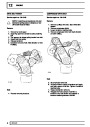
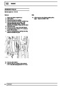
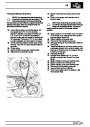
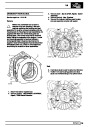
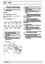
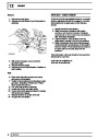
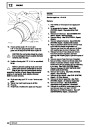
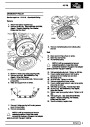
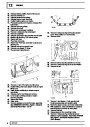
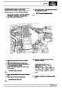
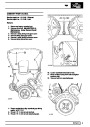
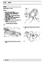
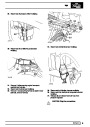
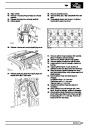
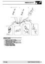
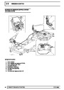
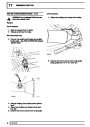
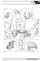
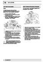
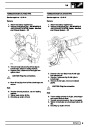
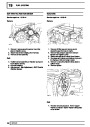
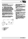
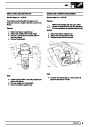
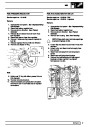
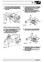
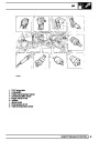
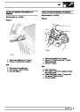
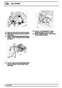
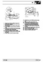
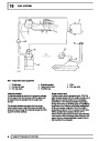
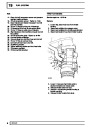
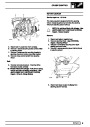
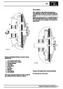
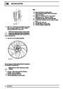
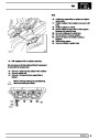
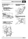
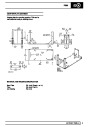
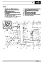
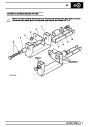
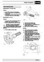
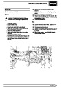
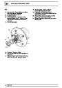
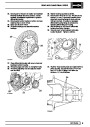
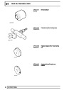
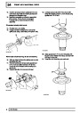
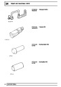
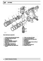
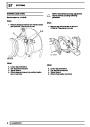
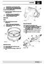
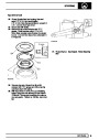
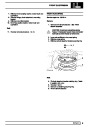
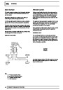
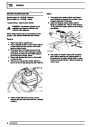
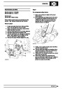
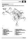
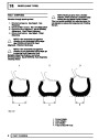
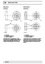
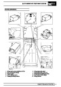
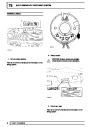
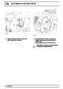
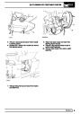
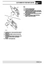
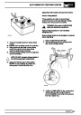
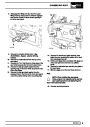
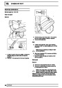
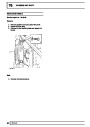
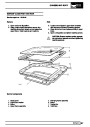
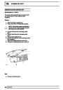
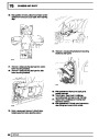
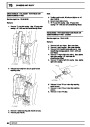
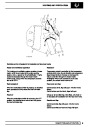
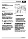
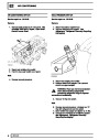
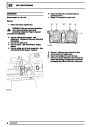
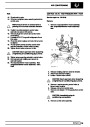
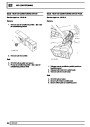
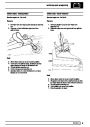
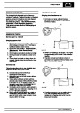
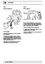
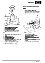
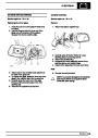
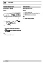
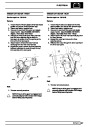
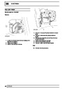
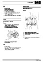
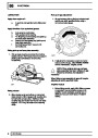
Align direction indicator cancellation bush. If
original rotary coupler is being fitted remove
adhesive tape and then fit rotary coupler to
column switch assembly.
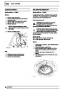
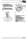
NOTE: If original rotary coupler is to be
fitted and there is evidence of tampering, it
is imperative that the coupler is
centralised. See rotary coupler centralise.
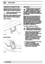
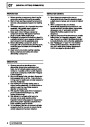
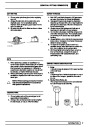
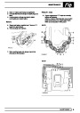
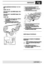
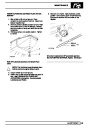
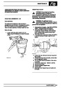
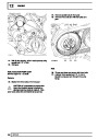
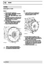
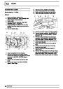
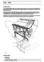
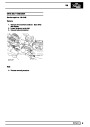
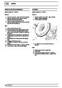
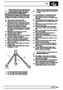
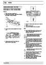
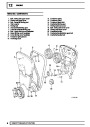
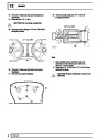
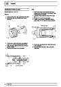
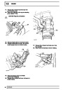
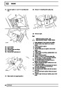
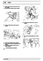
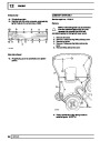
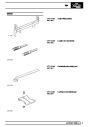
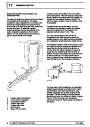
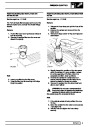
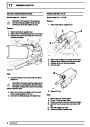
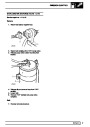
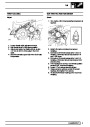
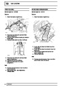
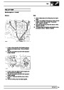
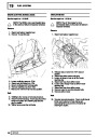
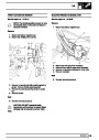
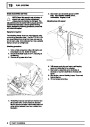
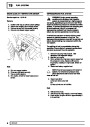
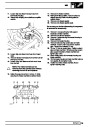
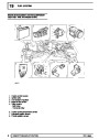
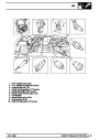
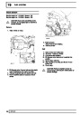
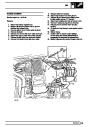
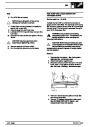
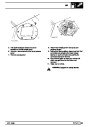
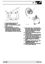
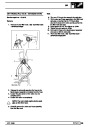
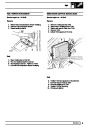
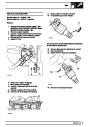
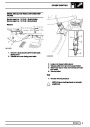
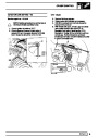
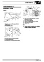
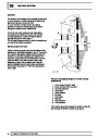
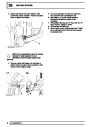
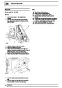
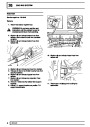
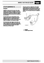
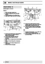
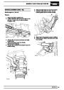
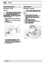
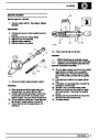
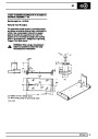
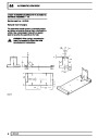
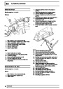
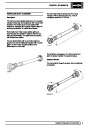
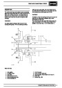
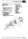
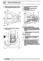
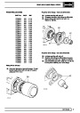
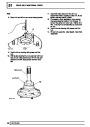
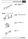
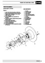
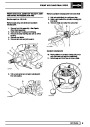
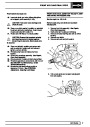
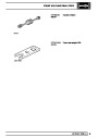
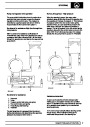
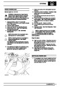
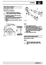
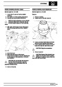
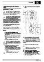
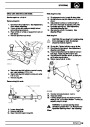
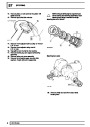
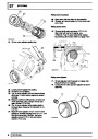
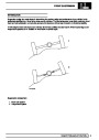
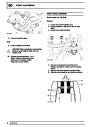
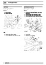
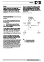
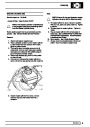
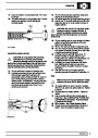
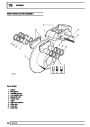
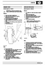
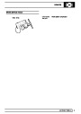
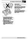
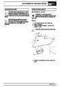
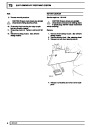
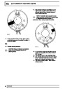
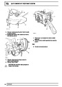
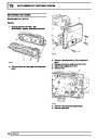
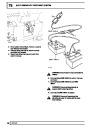
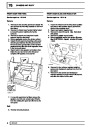
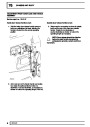
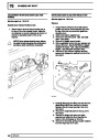
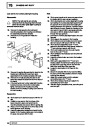
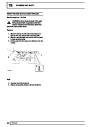
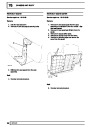
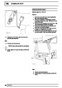
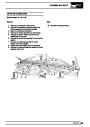
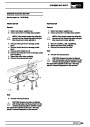
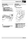
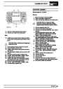
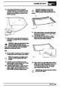
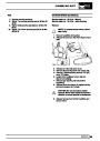
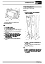
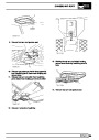
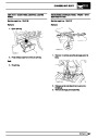
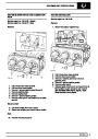
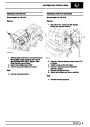
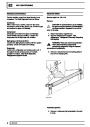
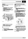
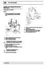
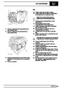
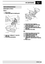
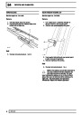
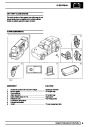
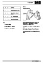
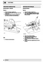
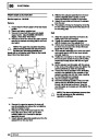
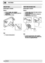
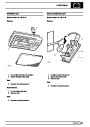
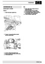
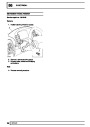
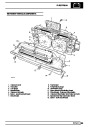
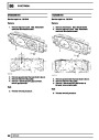
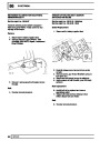
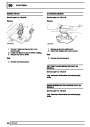
11.
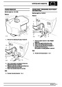
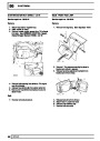
If rotary coupler is being re-used, place a piece
of adhesive tape around moulding in position A
to prevent rotation.
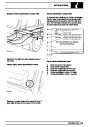
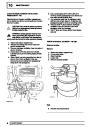
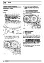
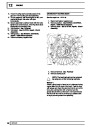
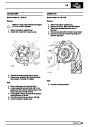
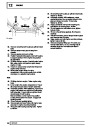
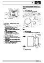
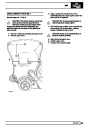
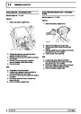
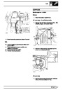
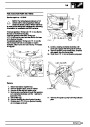
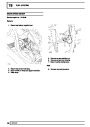
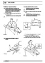
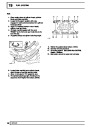
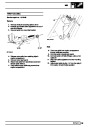
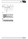
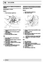
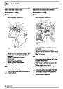
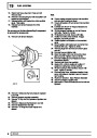
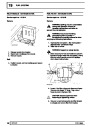
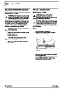
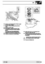
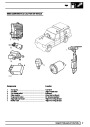
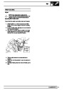
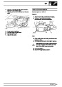
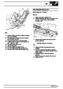
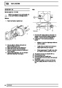
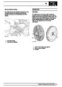
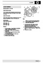
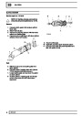
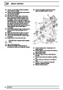
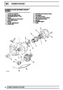
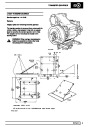
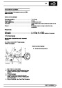
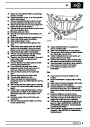
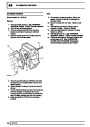
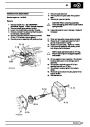
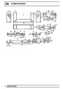
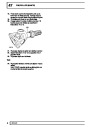
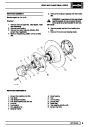
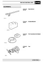
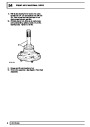
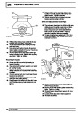
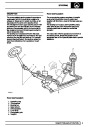
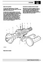
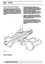
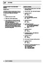
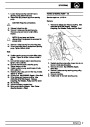
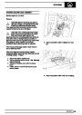
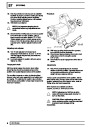
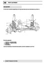
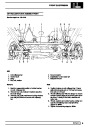
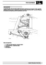
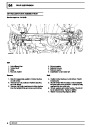
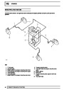
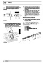
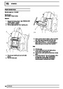
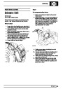
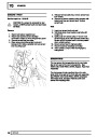
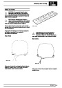
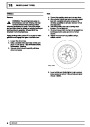
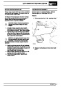
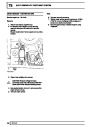
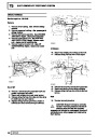
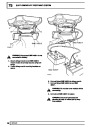
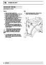
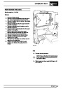
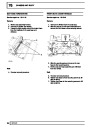
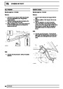
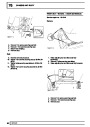
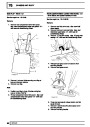
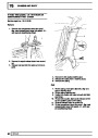
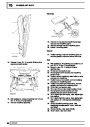
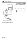
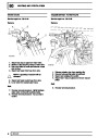
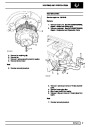
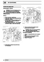
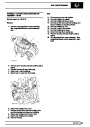
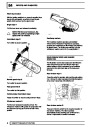
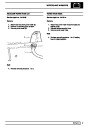
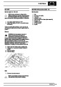
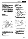
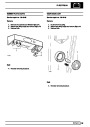
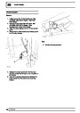
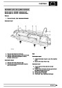
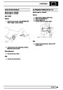
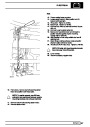
Refit
12.
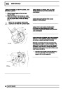
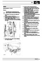
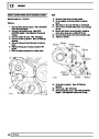
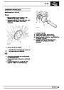
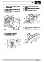
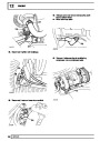
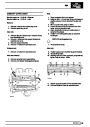
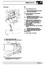
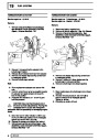
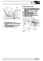
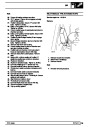
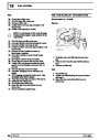
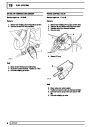
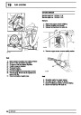
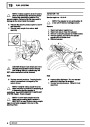
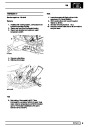
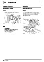
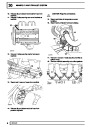
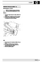
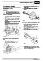
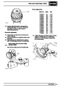
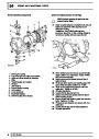
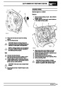
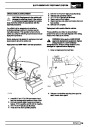
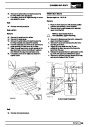
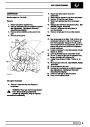
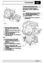
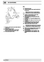
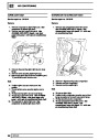
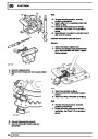
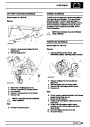
Reverse removal procedure.
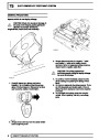
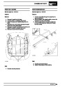
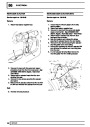
CAUTION: Ensure indicator cancellation
pegs correctly engage into back of
steering wheel.
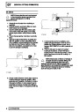
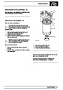
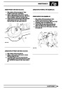
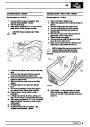
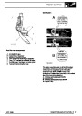
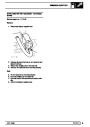
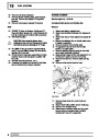
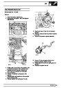
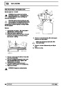
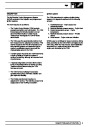
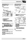
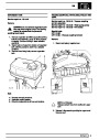
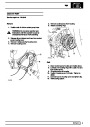
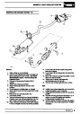
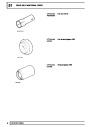
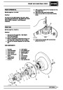
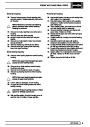
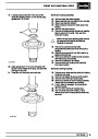
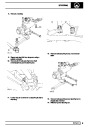
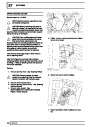
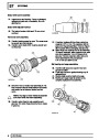
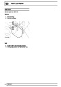
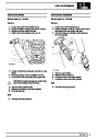
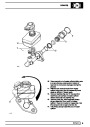
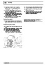
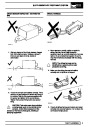
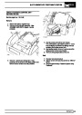
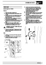
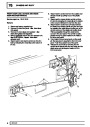
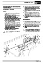
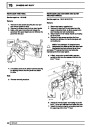
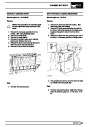
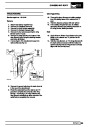
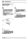
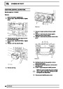
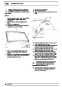
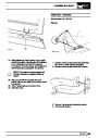
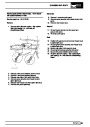
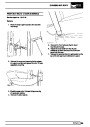
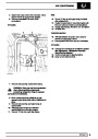
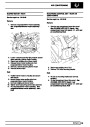
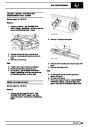
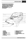
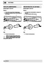
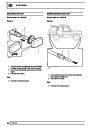
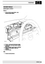
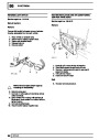
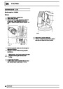
14. If a new rotary coupler is being fitted and the
sealing tape at position B is broken it MUST
NOT be used.
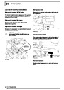
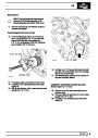
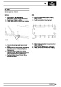
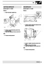
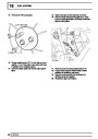
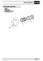
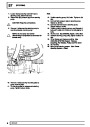
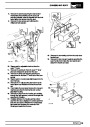
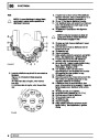
15.
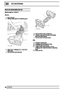
16.
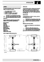
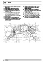
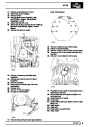
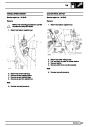
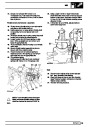
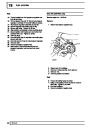
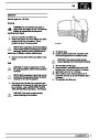
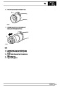
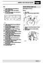
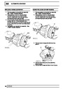
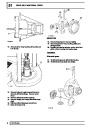
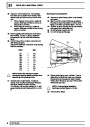
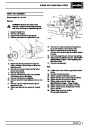
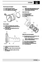
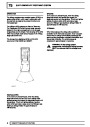
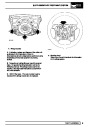
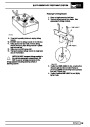
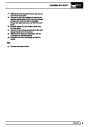
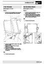
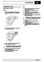
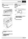
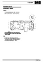
Refit steering wheel. See steering wheel.
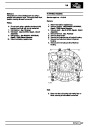
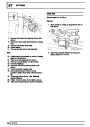
Turn steering wheel to both LH and RH lock 5
times. If adverse noises can be heard, check
alignment of indicator cancellation pegs.
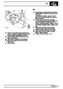
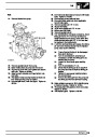
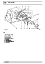
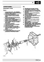
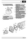
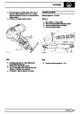
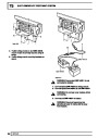
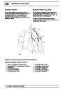
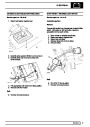
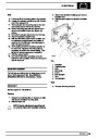
Refit driver’s airbag module. See driver’s
airbag module.
17.
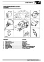
6
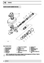
REPAIR
| Categories | Range Rover |
|---|---|
| Tags | Land Rover |
| Model Year | 1998 |
| Download File |
|
| Document Type | Workshop Manual |
| Language | English |
| Product Brand | Land Rover |
| Document File Type | |
| Publisher | landrover.com |
| Wikipedia's Page | http://en.wikipedia.org/wiki/Land_Rover |
| Copyright | Attribution Non-commercial |
(0 votes, average: 0 out of 5)