


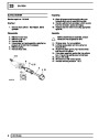


BRAKES
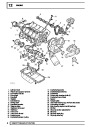
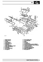
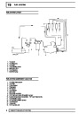
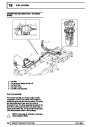
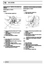
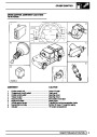
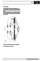
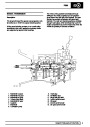
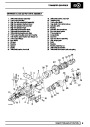
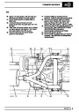
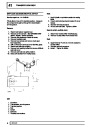
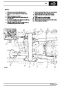
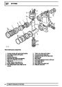
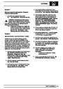
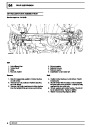
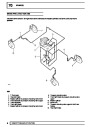
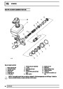
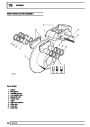
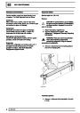
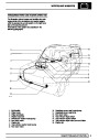
Description of components
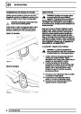
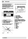
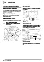
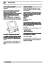
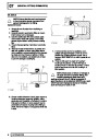
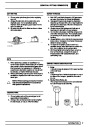
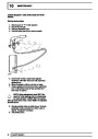
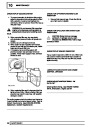
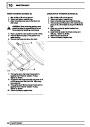
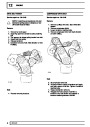
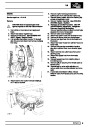
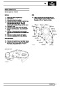
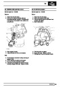
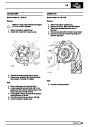
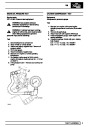
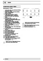
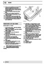
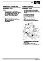
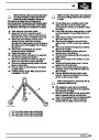
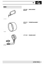
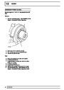
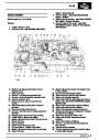
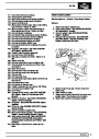
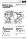
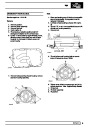
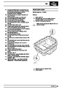
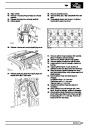
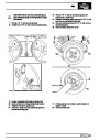
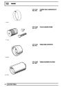
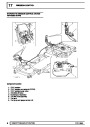
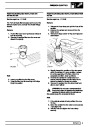
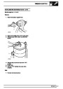
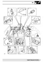
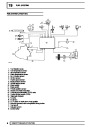
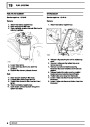
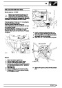
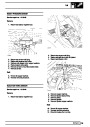
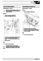
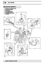
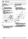
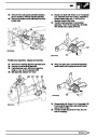
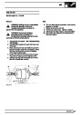
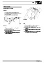
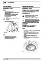
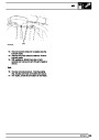
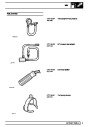
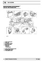
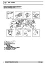
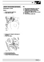
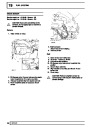
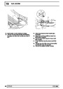
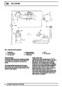
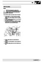
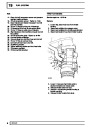
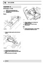
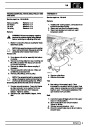
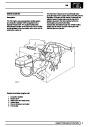
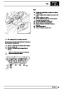
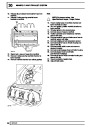
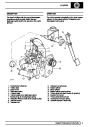
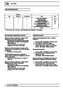
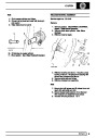
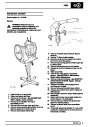
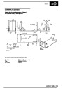
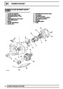
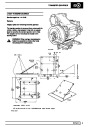
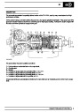
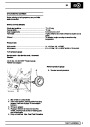
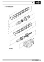
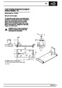
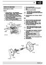
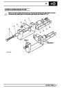
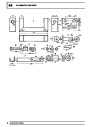
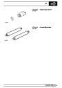
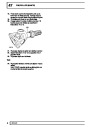
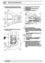
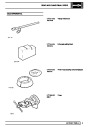
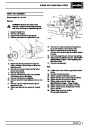
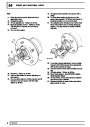
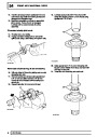
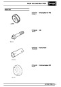
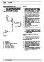
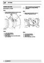
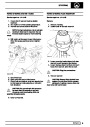
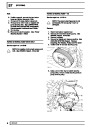
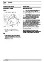
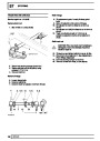
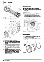
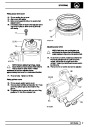
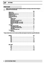
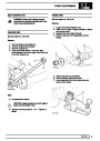
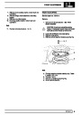
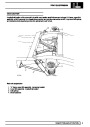
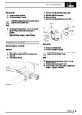
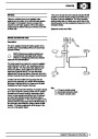
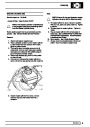
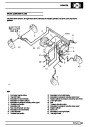
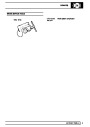
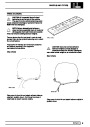
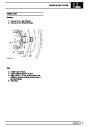
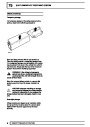
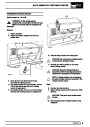
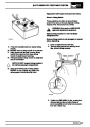
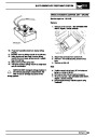
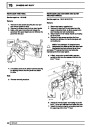
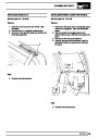
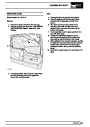
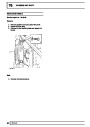
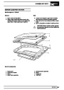
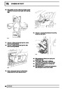
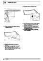
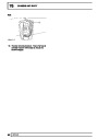
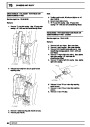
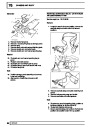
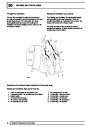
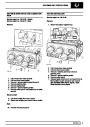
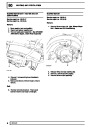
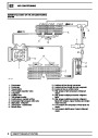
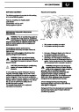
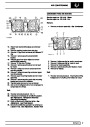
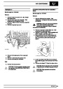
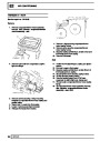
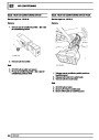
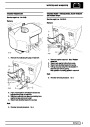
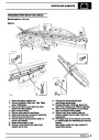
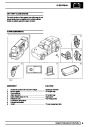
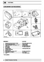
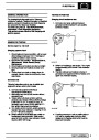
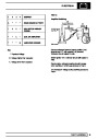
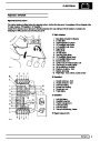
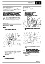
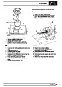
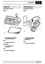
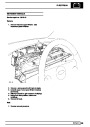
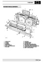
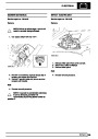
ABS Modulator unit
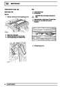
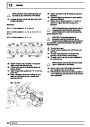
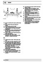
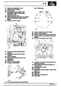
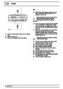
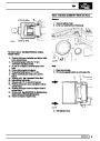
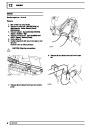
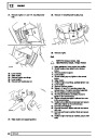
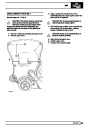
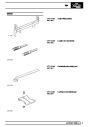
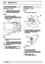
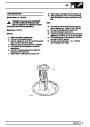
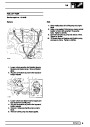
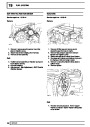
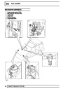
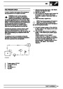
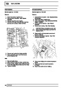
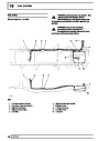
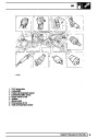
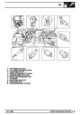
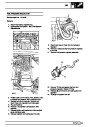
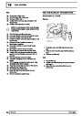
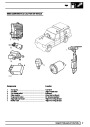
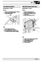
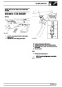
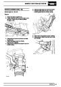
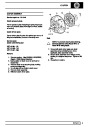
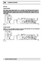
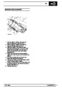
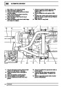
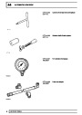
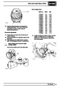
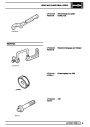
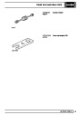
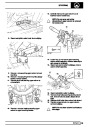
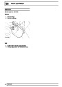
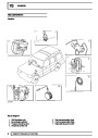
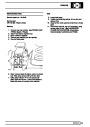
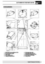
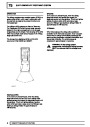
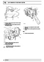
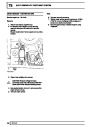
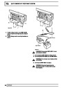
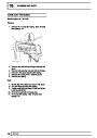
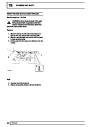
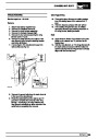
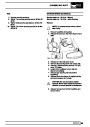
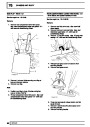
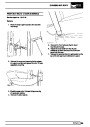
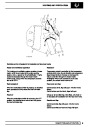
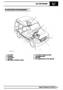
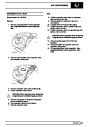
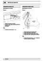
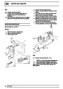
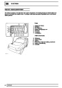
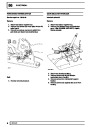
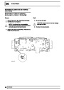
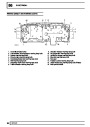
7. Diagnostic plug connection
1.
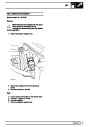
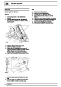
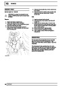
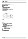
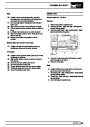
A diagnostic plug is located behind the dash. To the
left of the steering column on LHD vehicles. To the
right of the steering column on RHD vehicles. It is a 5
way blue connector.
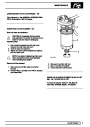
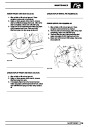
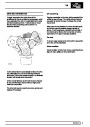
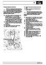
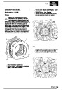
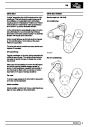
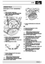
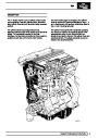
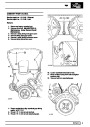
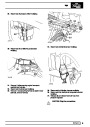
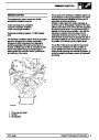
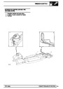
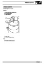
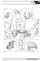
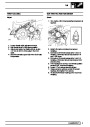
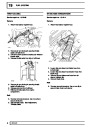
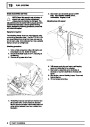
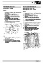
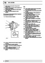
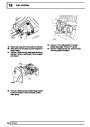
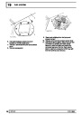
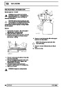
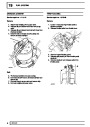
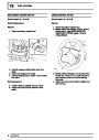
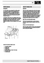
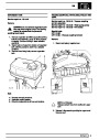
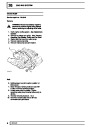
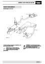
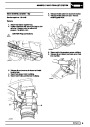
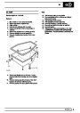
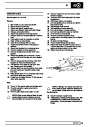
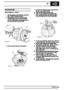
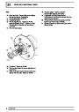
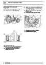
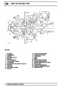
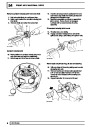
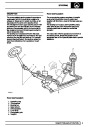
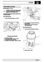
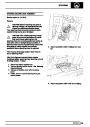
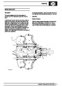
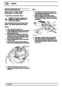
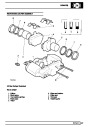
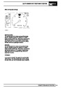
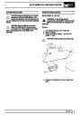
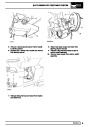
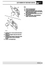
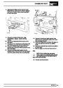
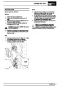
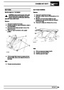
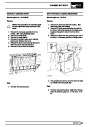
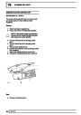
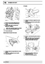
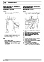
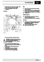
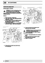
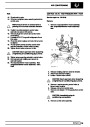
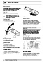
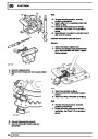
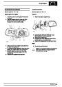
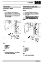
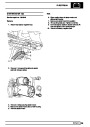
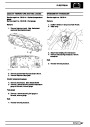
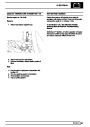
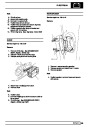
To provide the ABS function a Modulator is positioned
within the system between the master cylinder and the
calipers. On both LHD and RHD vehicles it is sited on
the left inner wing [fender]. The Modulator has 8
solenoid valves, 2 for each wheel, 2 expanders and a
recirculation pump. It is non serviceable.
The location and identification of ABS electrical relays
are given in the Electrical Troubleshooting Manual.
For location and identification of ABS electrical fuses.
See ELECTRICAL, Repair, Fuse Box - Interior or.
See ELECTRICAL, Repair, Fuse Box - Engine
Compartment
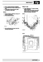
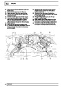
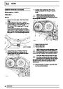
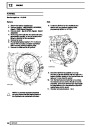
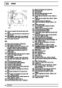
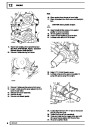
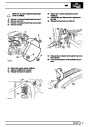
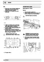
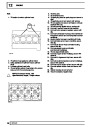
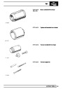
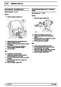
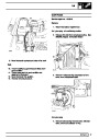
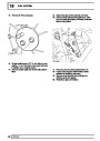
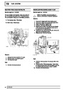
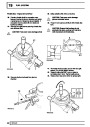
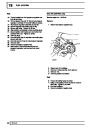
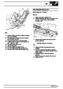
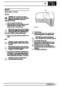
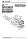
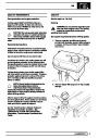
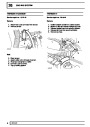
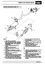
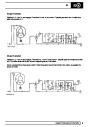
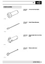
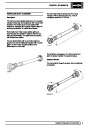
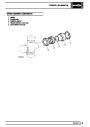
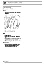
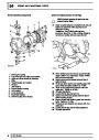
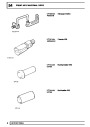
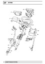
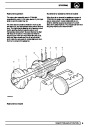
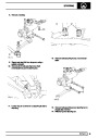
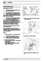
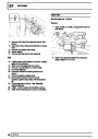
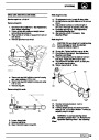
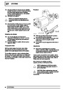
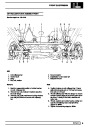
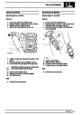
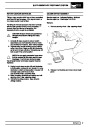
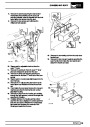
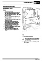
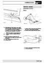
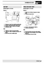
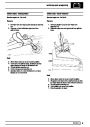
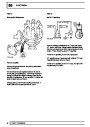
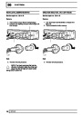
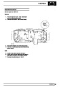
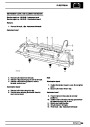
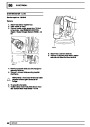
2.
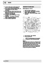
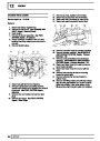
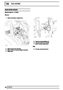
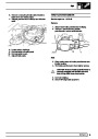
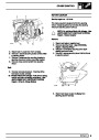
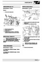
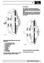
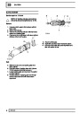
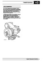
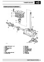
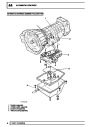
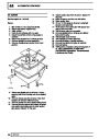
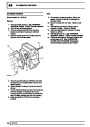
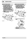
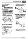
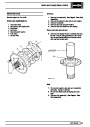
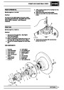
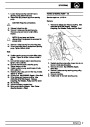
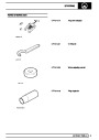
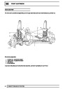
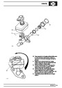
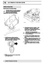
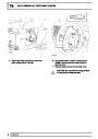
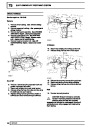
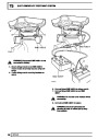
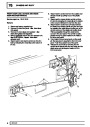
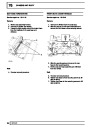
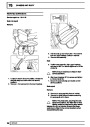
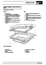
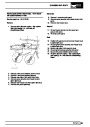
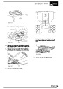
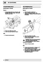
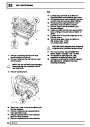
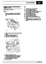
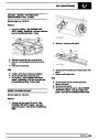
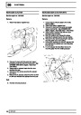
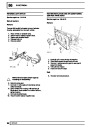
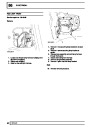
Servo/master cylinder
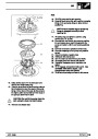
Actuation of the system is provided by a combined
master cylinder and servo assembly attached to the
pedal box, this provides pressure to opposed piston
calipers at each brake pad Twin piston at the front
axle, single piston at the rear.
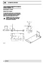
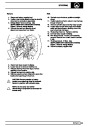
ANTI-LOCK BRAKE SYSTEM - ABS
Manufactured by WABCO
Introduction
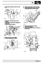
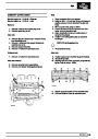
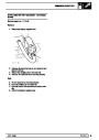
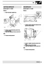
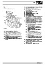
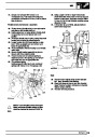
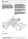
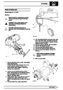
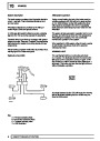
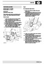
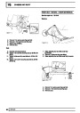
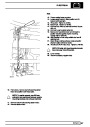
3.
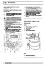
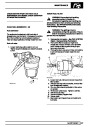
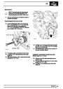
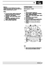
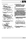
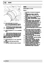
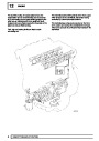
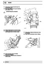
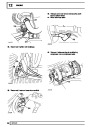
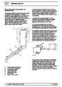
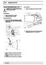
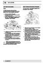
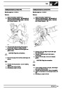
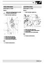
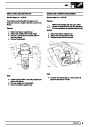
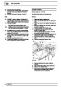
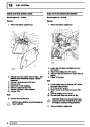
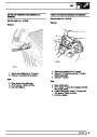
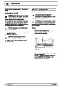
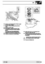
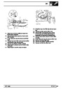
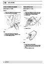
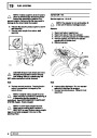
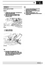
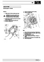
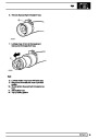
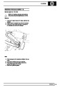
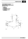
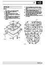
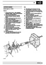
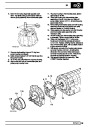
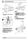
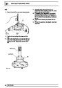
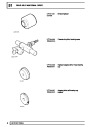
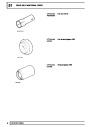
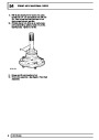
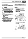
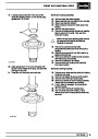
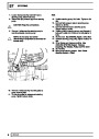
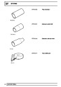
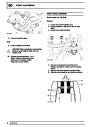
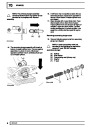
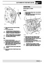
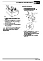
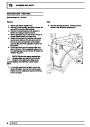
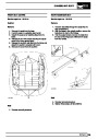
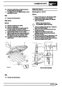
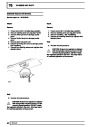
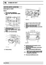
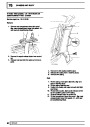
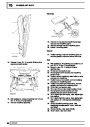
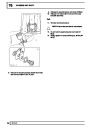
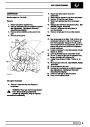
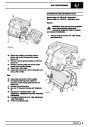
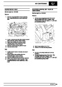
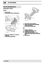
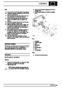
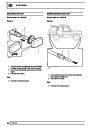
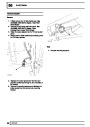
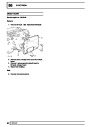
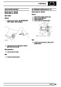
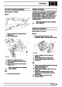
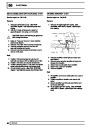
Pressure reducing valve
To maintain the braking balance, pressure to the rear
axle is regulated by a Pressure Reducing Valve (PRV)
This PRV is of the failure bypass type, allowing full
system pressure to the rear axle in the event of a front
circuit failure. It is sited on the left inner wing [fender].
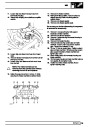
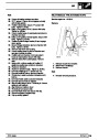
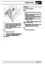
The purpose of ABS is to prevent vehicle wheels
locking during brake application, thus maintaining
vehicle steerability and stability. This allows vehicle to
be steered whilst brakes are applied, even under
emergency conditions, and to avoid obstacles where
there is sufficient space to redirect the vehicle.
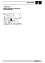
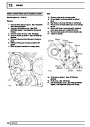
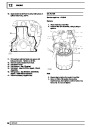
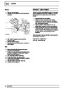
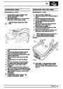
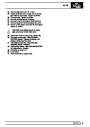
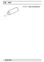
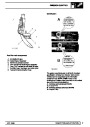
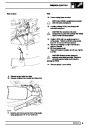
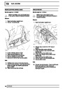
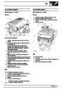
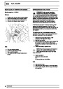
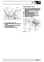
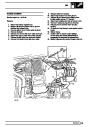
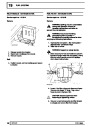
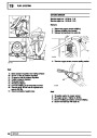
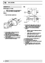
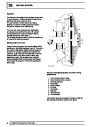
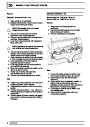
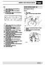
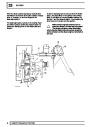
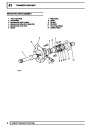
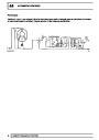
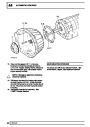
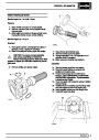
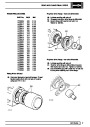
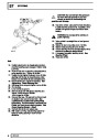
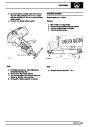
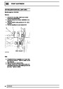
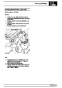
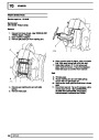
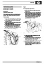
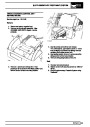
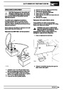
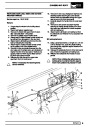
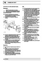
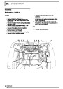
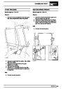
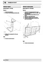
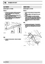
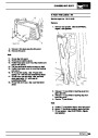
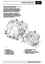
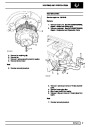
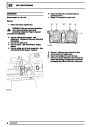
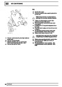
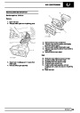
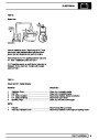
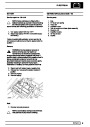
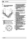
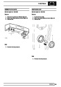
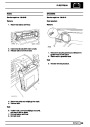
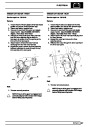
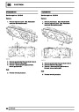
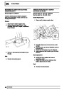
4.
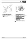
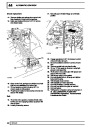
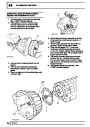
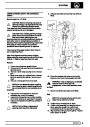
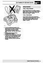
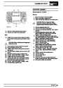
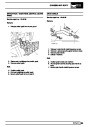
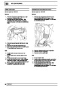
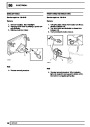
Electronic control unit - ECU
ABS control is provided by an electronic control unit
which is positioned on the passenger side of the
vehicle behind the dash panel/glove box.
The ECU, which is non-serviceable, is connected to
the ABS harness by a 35 way connector. non
serviceable.
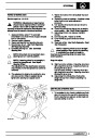
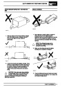
WARNING: ABS is an aid to retaining
steering control and stability while
braking.
•
•
ABS cannot defy the natural laws of physics
acting on the vehicle.
The ECU continually monitors the brake system,
providing diagnostics in the event of a system
malfunction. Details of how to access the ECU
diagnostics are provided in the Electrical
Troubleshooting Manual.
ABS will not prevent accidents resulting from
excessive cornering speeds, following
another vehicle too closely or aquaplaning,
i.e. where a layer of water prevents adequate
contact between tyre and road surface.
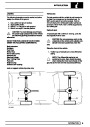
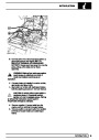
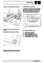
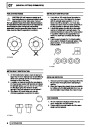
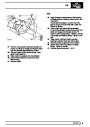
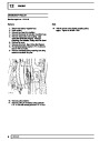
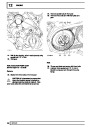
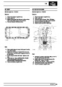
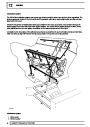
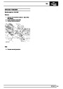
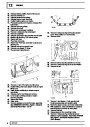
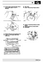
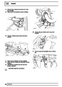
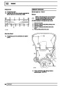
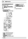
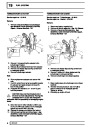
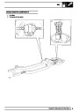
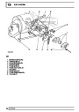
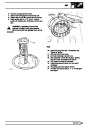
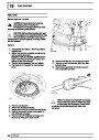
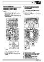
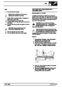
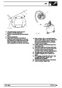
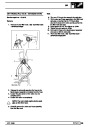
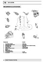
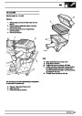
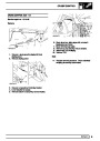
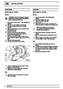
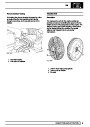
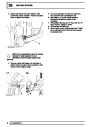
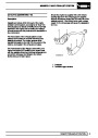
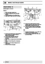
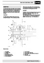
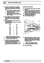
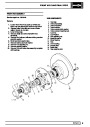
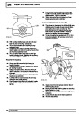
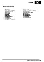
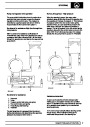
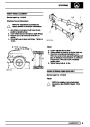
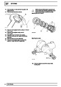
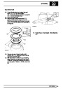
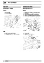
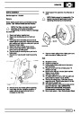
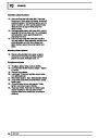
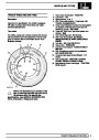
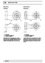
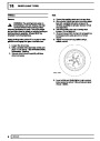
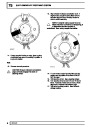
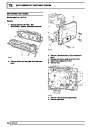
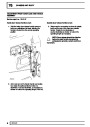
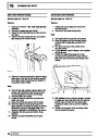
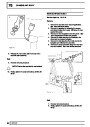
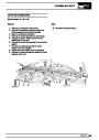
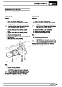
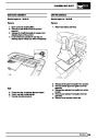
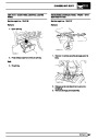
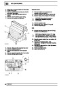
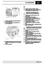
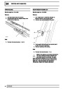
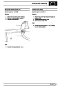
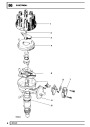
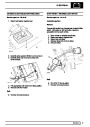
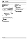
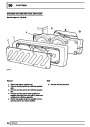
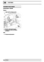
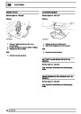
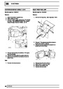
5.&
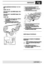
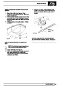
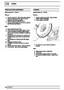
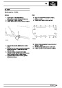
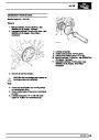
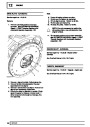
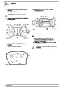
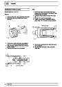
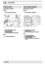
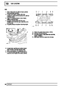
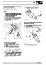
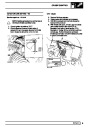
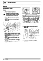
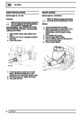
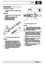
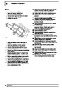
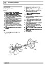
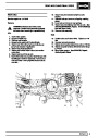
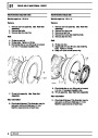
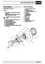
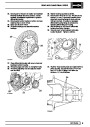
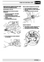
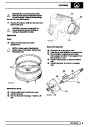
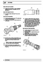
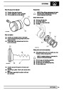
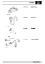
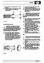
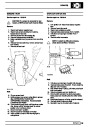
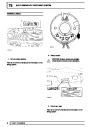
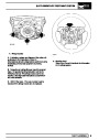
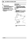
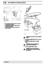
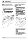
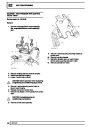
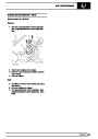
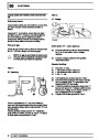
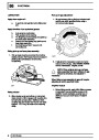
6. Front and rear sensors/exciter rings - 4 off
•
•
The additional control provided by ABS must
never be exploited in a dangerous or
reckless manner which could jeopardise the
safety of driver or other road users.
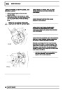
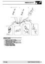
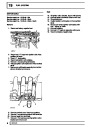
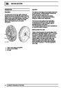
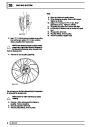
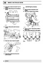
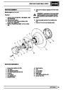
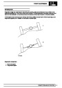
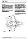
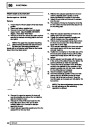
A sensor is sited at each wheel, sensing a 60 tooth
exciter ring. When vehicle is in motion inductive
sensors send signals to ECU. Front exciter ring is
fitted to outside diameter of constant velocity joint
inside each front hub assembly. The rear exciter ring
is bolted to the rear of each brake disc bell.
The fitting of ABS does not imply that the
vehicle will always stop in a shorter stopping
distance.
DESCRIPTION AND OPERATION
3
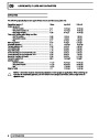
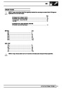
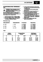
| Categories | Range Rover |
|---|---|
| Tags | Land Rover |
| Model Year | 1998 |
| Download File |
|
| Document Type | Workshop Manual |
| Language | English |
| Product Brand | Land Rover |
| Document File Type | |
| Publisher | landrover.com |
| Wikipedia's Page | http://en.wikipedia.org/wiki/Land_Rover |
| Copyright | Attribution Non-commercial |
(0 votes, average: 0 out of 5)