


54
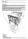
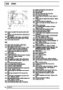
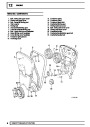
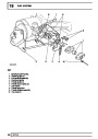
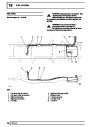
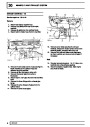
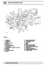
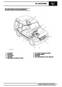
FRONT AXLE AND FINAL DRIVE
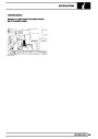
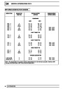
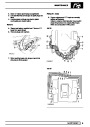
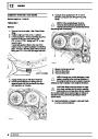
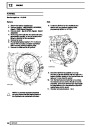
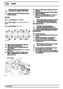
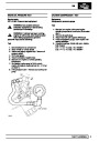
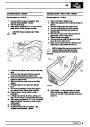
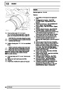
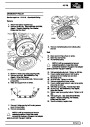
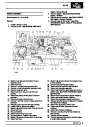
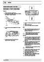
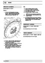
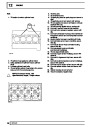
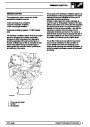
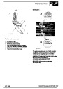
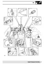
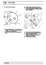
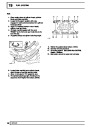
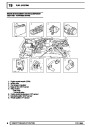
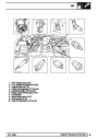
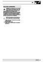
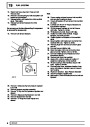
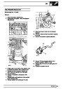
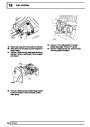
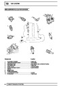
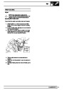
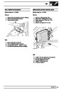
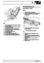
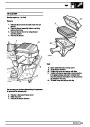
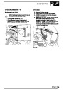
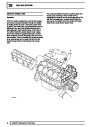
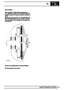
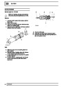
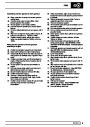
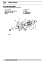
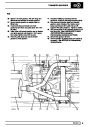
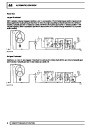
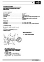
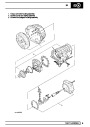
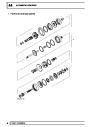
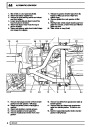
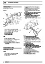
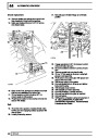
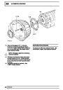
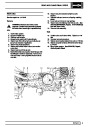
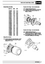
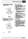
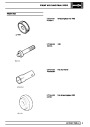
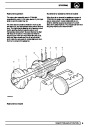
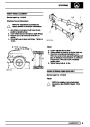
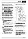
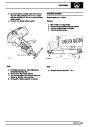
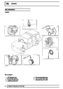
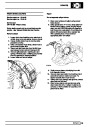
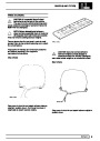
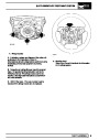
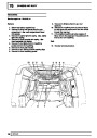
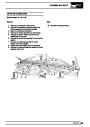
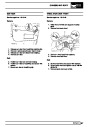
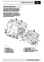
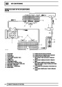
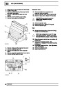
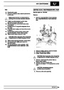
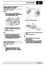
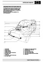
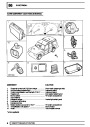
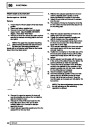
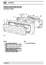
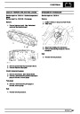
Remove constant velocity joint from axle shaft
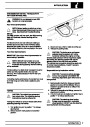
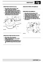
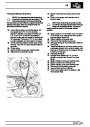
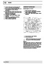
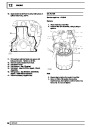
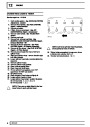
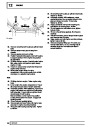
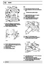
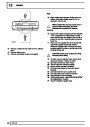
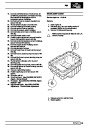
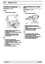
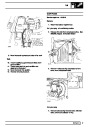
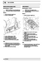
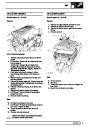
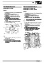
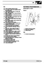
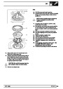
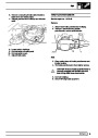
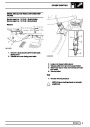
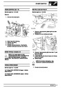
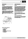
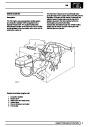
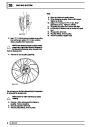
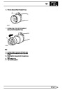
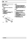
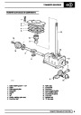
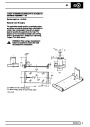
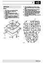
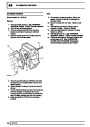
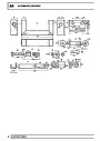
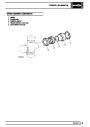
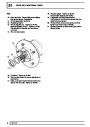
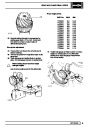
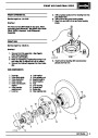
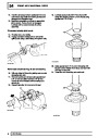
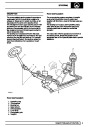
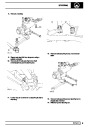
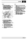
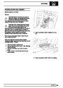
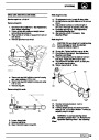
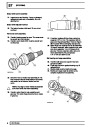
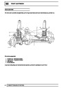
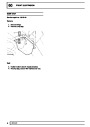
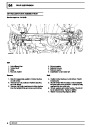
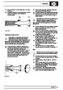
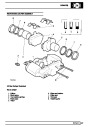
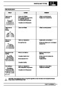
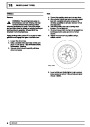
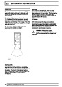
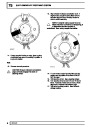
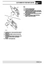
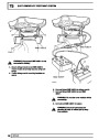
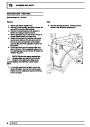
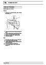
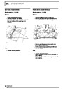
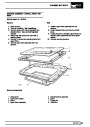
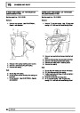
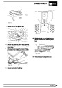
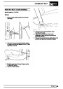
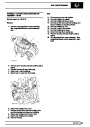
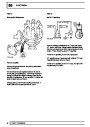
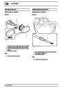
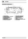
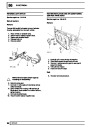
12. Examine all components in particular inner and
outer track, cage balls and bearing surfaces for
damage and excessive wear.
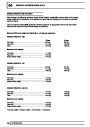
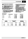
13. Maximum acceptable end-float on assembled
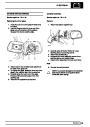
joint 0,64mm. Renew if worn or damaged.
Lubricate with a recommended oil during
assembly.
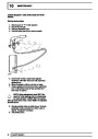
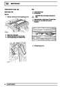
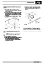
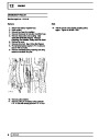
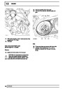
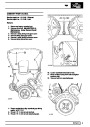
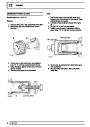
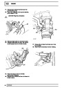
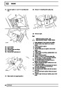
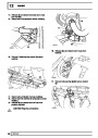
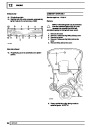
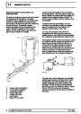
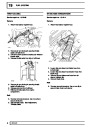
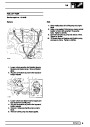
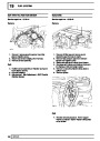
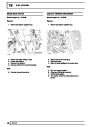
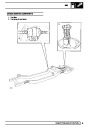
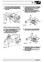
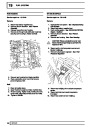
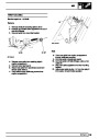
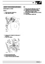
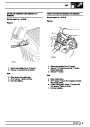
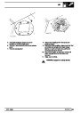
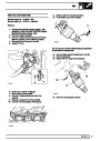
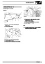
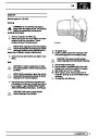
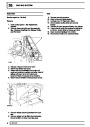
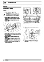
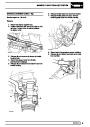
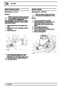
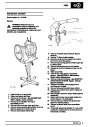
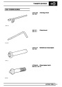
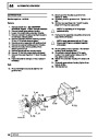
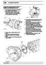
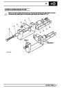
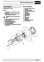
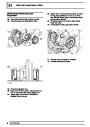
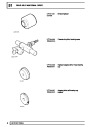
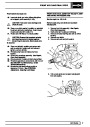
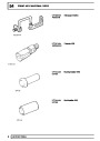
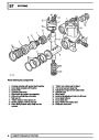
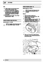
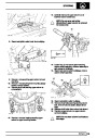
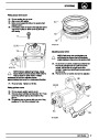
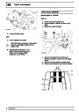
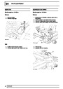
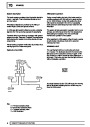
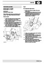
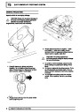
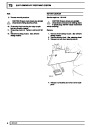
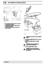
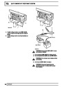
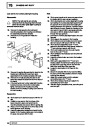
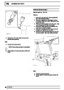
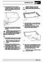
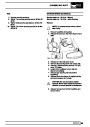
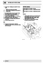
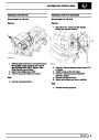
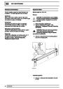
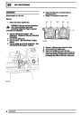
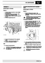
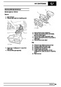
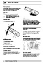
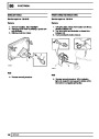
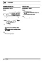
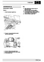
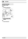
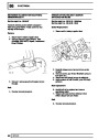
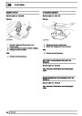
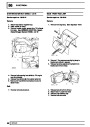
7.
8.
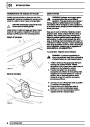
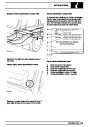
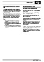
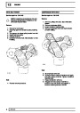
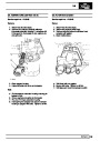
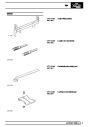
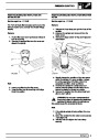
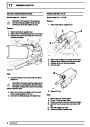
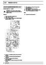
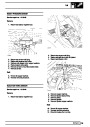
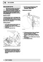
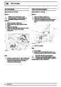
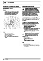
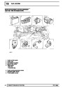
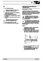
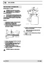
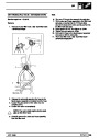
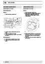
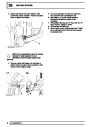
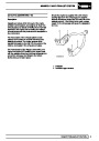
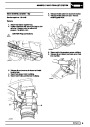
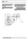
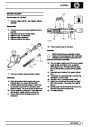
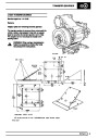
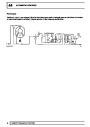
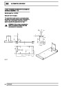
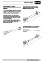
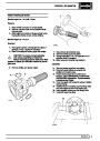
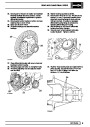
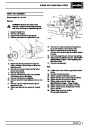
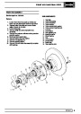
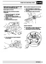
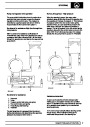
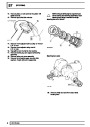
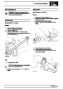
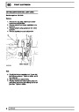
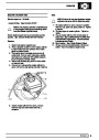
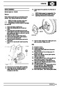
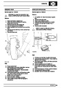
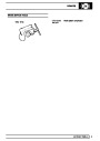
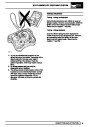
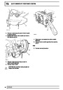
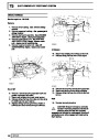
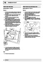
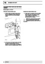
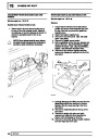
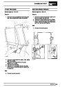
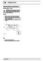
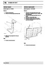
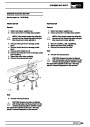
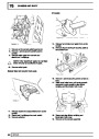
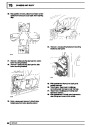
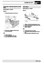
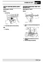
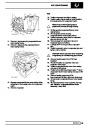
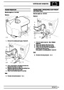
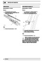
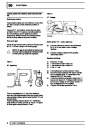
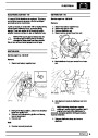
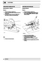
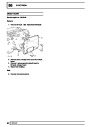
Hold axle shaft firmly in a soft jawed vice.
Using a soft mallet drive constant velocity joint
from shaft.
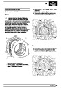
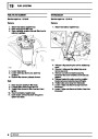
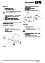
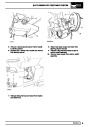
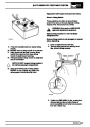
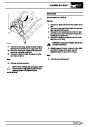
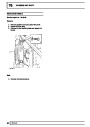
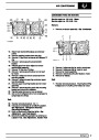
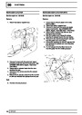
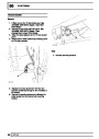
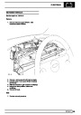
9.
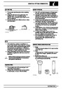
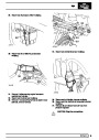
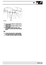
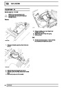
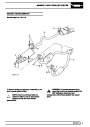
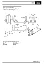
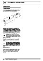
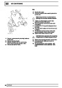
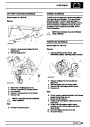
Remove circlip and collar from axle shaft.
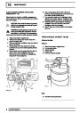
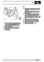
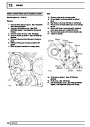
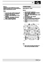
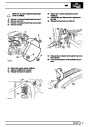
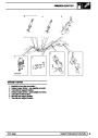
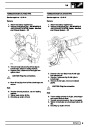
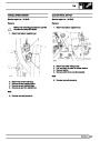
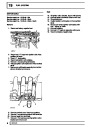
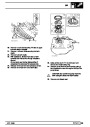
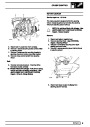
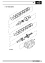
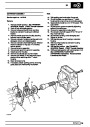
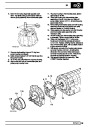
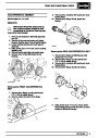
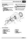
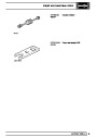
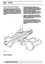
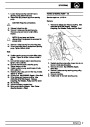
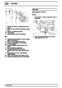
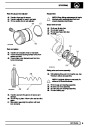
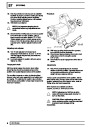
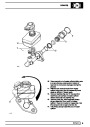
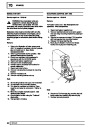
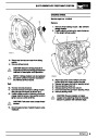
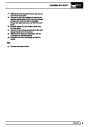
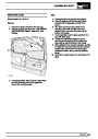
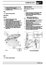
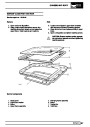
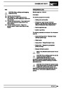
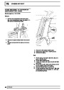
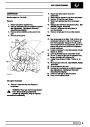
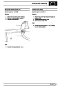
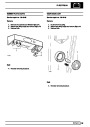
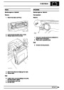
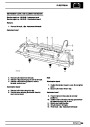
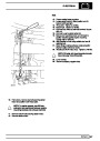
Fit constant velocity joint to axle
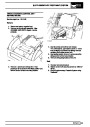
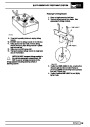
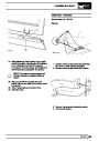
14.
15.
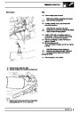
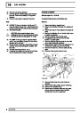
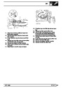
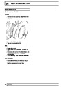
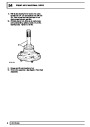
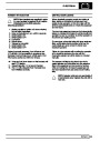
Fit collar and a new circlip.
Engage constant velocity joint on axle shaft
splines and using a soft mallet, drive joint in fully.
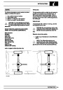
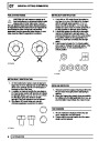
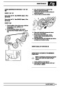
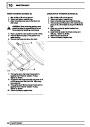
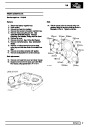
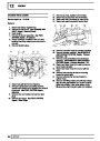
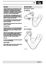
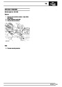
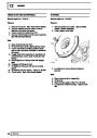
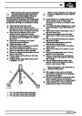
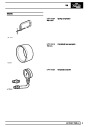
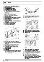
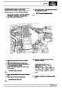
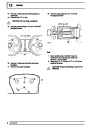
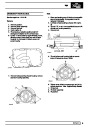
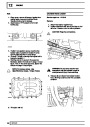
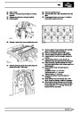
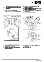
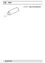
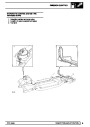
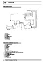
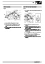
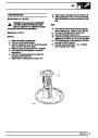
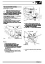
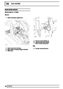
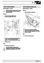
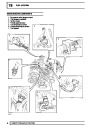
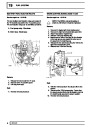
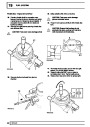
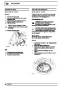
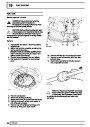
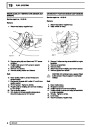
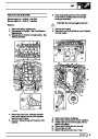
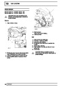
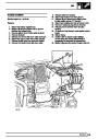
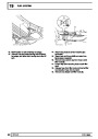
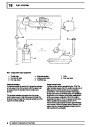
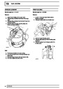
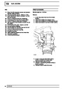
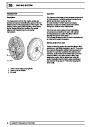
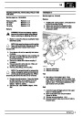
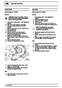
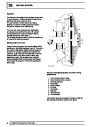
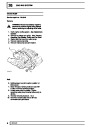
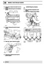
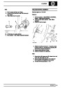
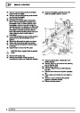
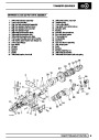
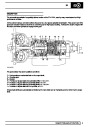
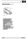
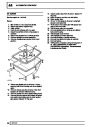
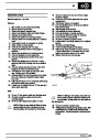
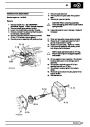
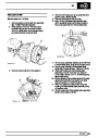
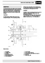
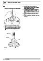
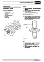
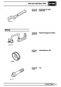
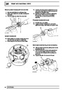
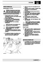
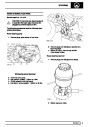
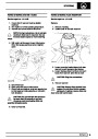
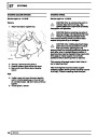
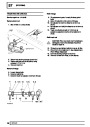
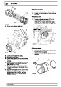
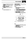
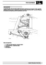
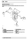
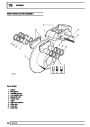
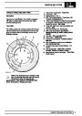
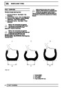
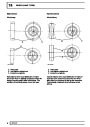
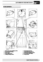
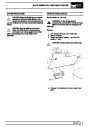
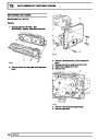
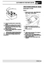
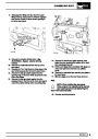
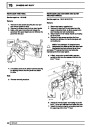
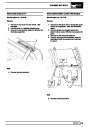
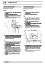
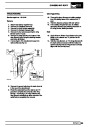
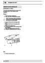
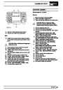
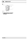
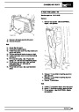
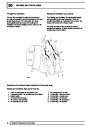
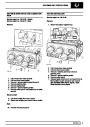
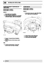
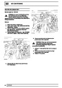
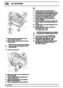
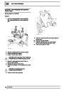
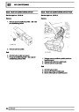
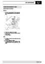
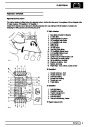
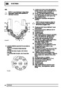
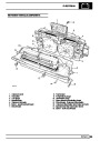
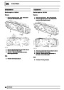
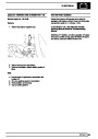
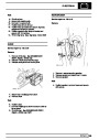
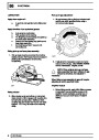
Constant velocity joint
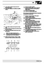
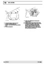
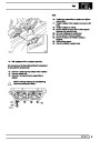
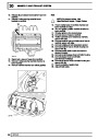
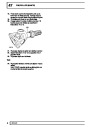
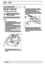
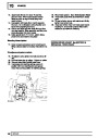
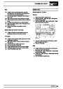
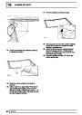
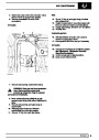
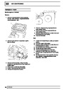
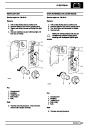
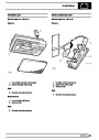
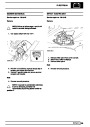
10.
11.
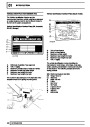
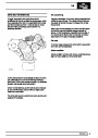
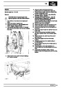
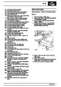
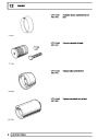
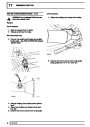
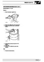
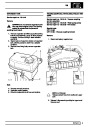
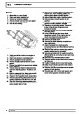
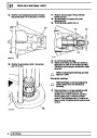
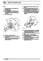
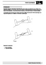
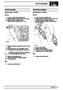
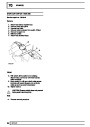
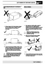
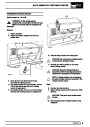
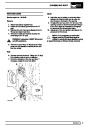
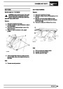
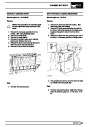
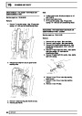
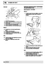
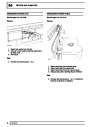
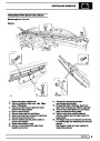
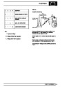
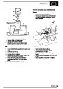
Mark positions of constant velocity joint, inner
and outer race and cage for reassembly.
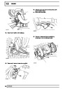
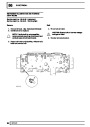
Swivel cage and inner race to remove balls.
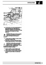
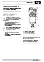
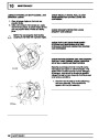
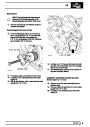
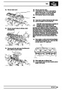
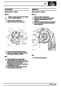
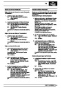
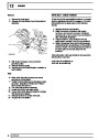
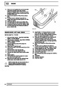
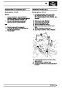
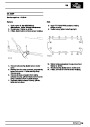
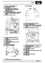
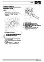
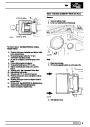
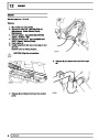
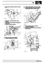
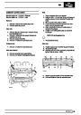
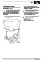
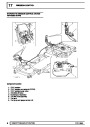
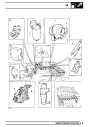
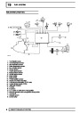
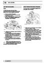
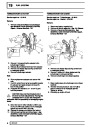
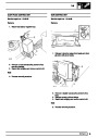
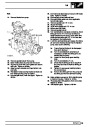
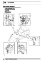
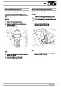
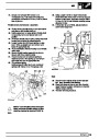
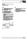
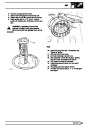
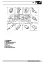
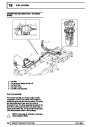
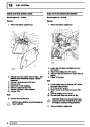
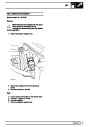
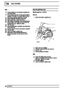
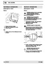
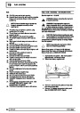
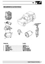
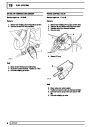
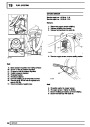
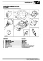
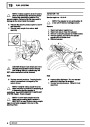
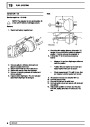
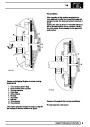
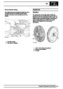
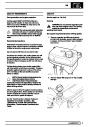
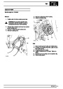
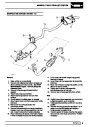
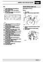
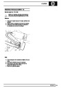
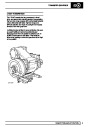
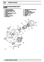
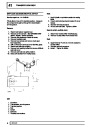
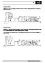
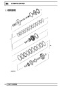
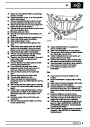
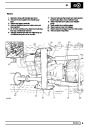
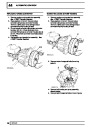
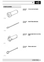
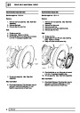
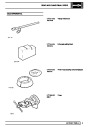
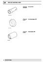
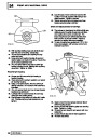
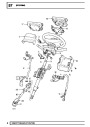
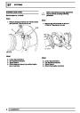
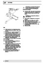
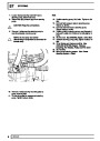
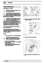
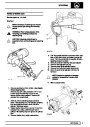
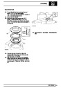
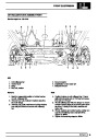
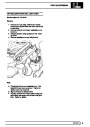
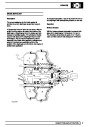
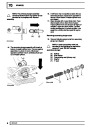
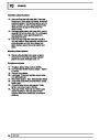
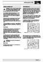
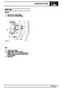
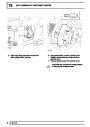
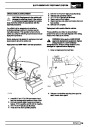
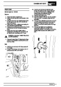
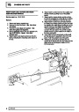
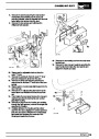
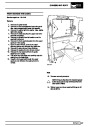
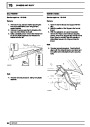
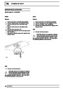
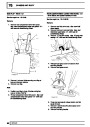
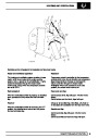
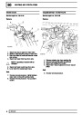
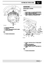
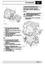
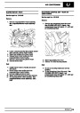
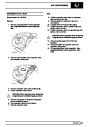
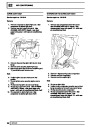
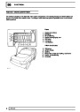
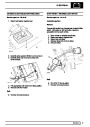
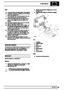
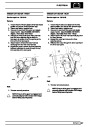
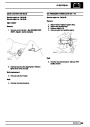
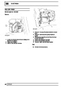
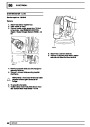
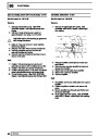
Renew stub axle,thrust ring, oil seal and bearing
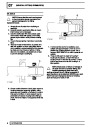
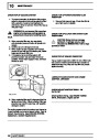
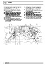
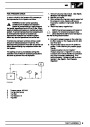
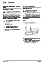
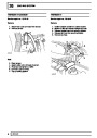
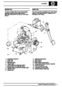
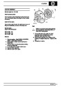
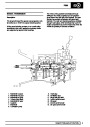
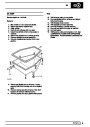
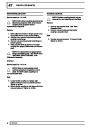
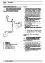
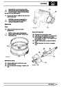
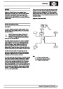
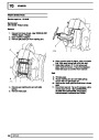
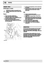
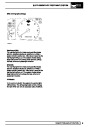
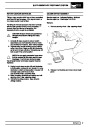
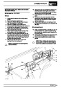
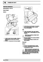
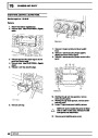
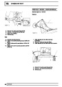
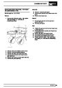
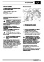
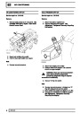
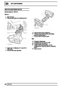
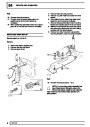
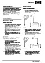
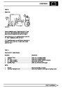
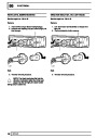
16.
17.
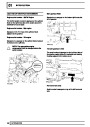
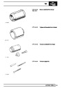
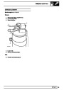
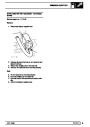
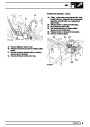
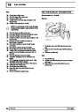
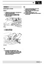
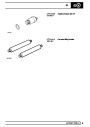
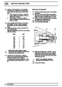
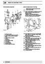
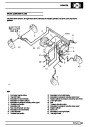
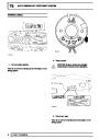
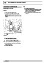
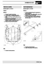
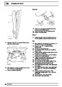
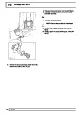
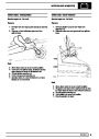
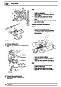
Drill and chisel off thrust ring taking care to avoid
damaging stub axle.
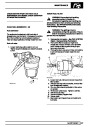
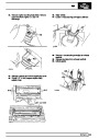
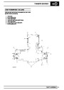
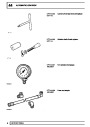
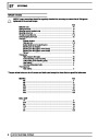
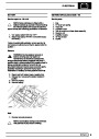
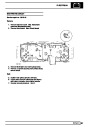
Remove bearing and oil seal using special tool
LRT-37-004 and slide hammer LRT-99-004.
Ensure lip of tool locates behind bearing to to
drive it out.
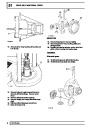
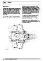
18.
Repeat instruction for removal of oil seal.
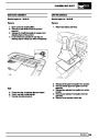
8
OVERHAUL
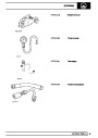
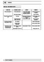
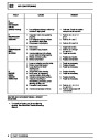
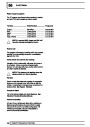
| Categories | Range Rover |
|---|---|
| Tags | Land Rover |
| Model Year | 1998 |
| Download File |
|
| Document Type | Workshop Manual |
| Language | English |
| Product Brand | Land Rover |
| Document File Type | |
| Publisher | landrover.com |
| Wikipedia's Page | http://en.wikipedia.org/wiki/Land_Rover |
| Copyright | Attribution Non-commercial |
(0 votes, average: 0 out of 5)