


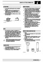


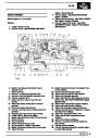
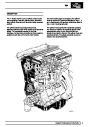
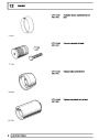
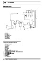


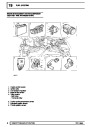
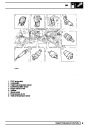


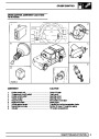
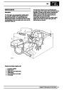


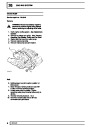

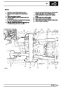


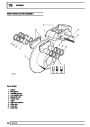

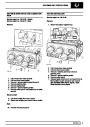

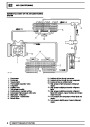
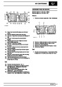

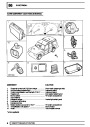
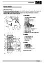
Mpi
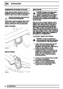
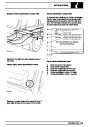
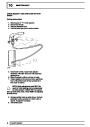
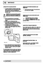
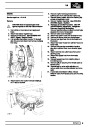
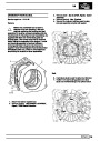
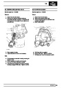
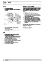
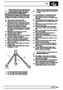
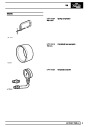
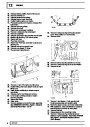
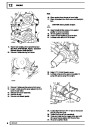
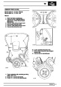
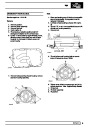
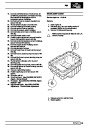
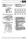
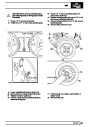
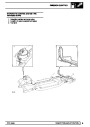
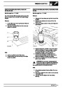
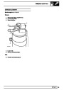
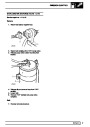
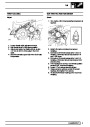
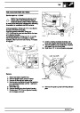
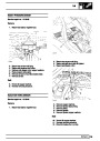
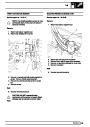
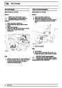
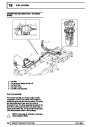
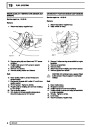
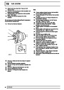
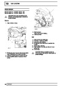
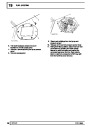
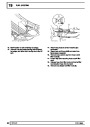
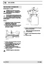
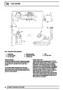
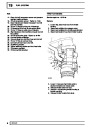
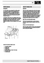
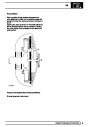
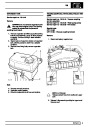
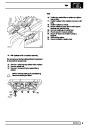
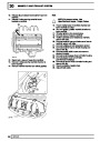
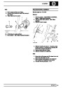
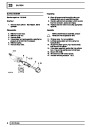
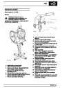
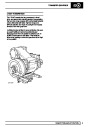
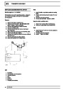
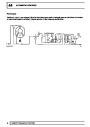
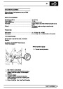
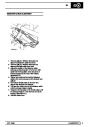
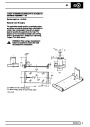
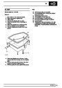
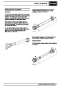
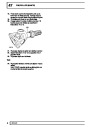
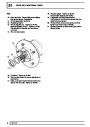
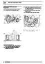
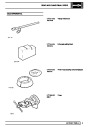
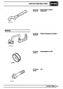
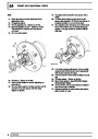
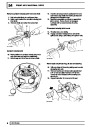
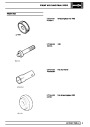
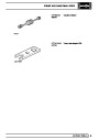
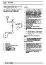
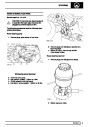
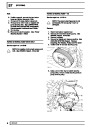
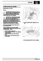
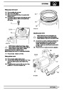
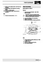
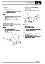
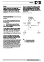
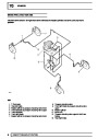
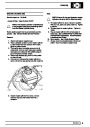
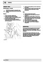
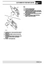
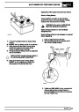
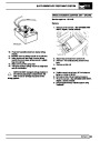
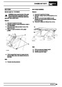
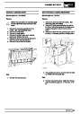
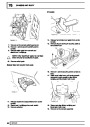
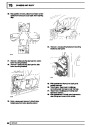
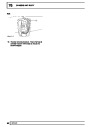
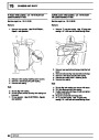
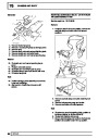
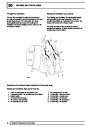
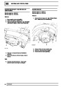
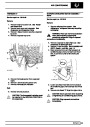
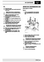
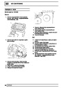
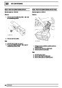
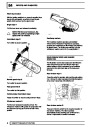
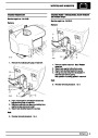
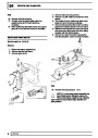
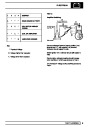
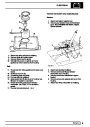
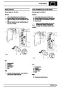
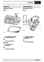
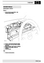
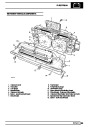
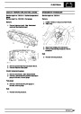
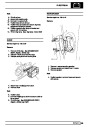
Fuel pump
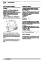
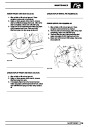
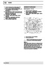
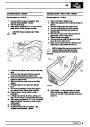
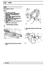
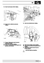
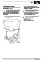
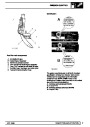
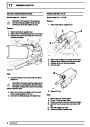
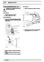
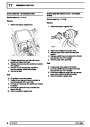
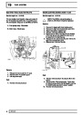
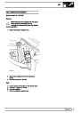
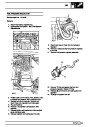
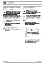
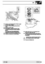
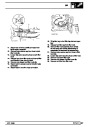
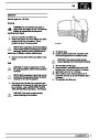
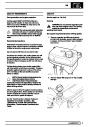
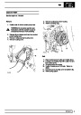
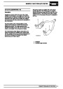
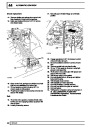
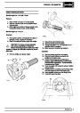
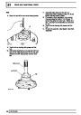
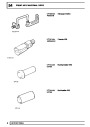
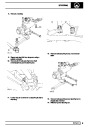
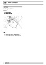
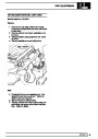
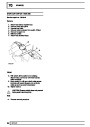
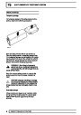
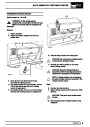
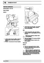
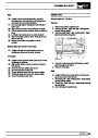
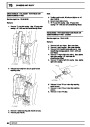
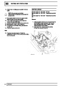
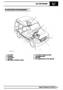
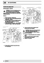
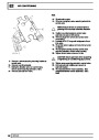
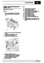
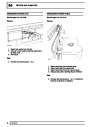
Inertia switch
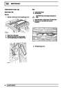
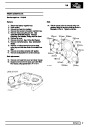
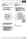
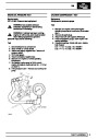
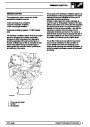
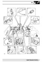
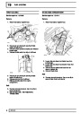
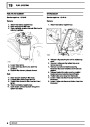
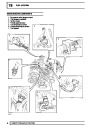
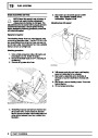
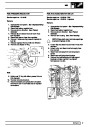
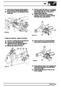
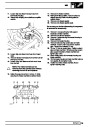
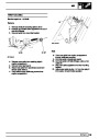
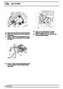
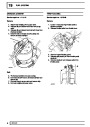
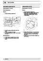
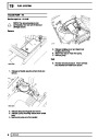
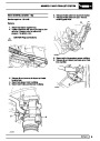
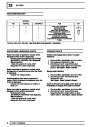
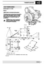
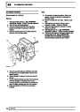
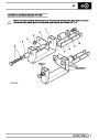
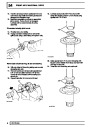
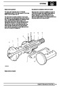
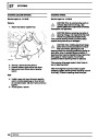
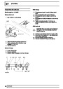
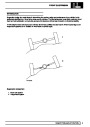
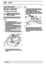
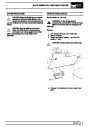
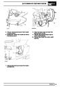
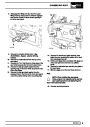
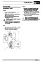
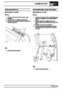
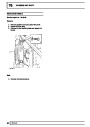
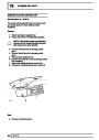
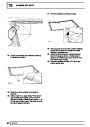
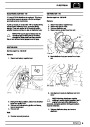
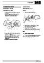
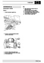
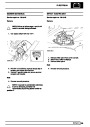
The electric fuel pump, located inside the fuel tank, is
a self-priming centrifugal ’wet’ pump, the motor and
pump are filled with fuel.
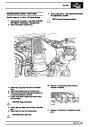
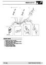
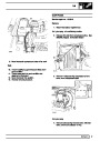
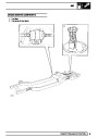
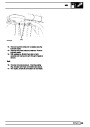
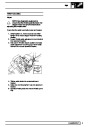
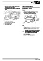
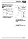
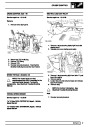
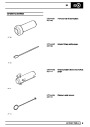
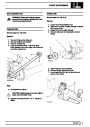
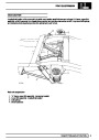
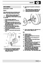
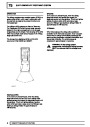
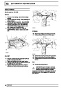
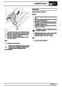
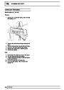
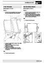
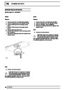
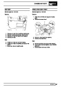
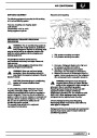
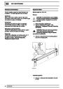
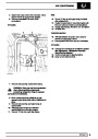
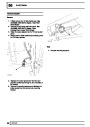
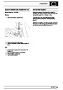
The fuel pump circuit incorporates an inertia switch
which in the event of sudden deceleration isolates the
power supply to the fuel pump. The inertia switch is
situated in the engine compartment on the bulkhead
and can, if tripped, be reset by depressing the central
plunger.
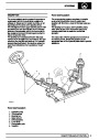
The fuel pump supplies more fuel than the maximum
load requirement for the engine, so that pressure in
the fuel system can be maintained under all
conditions.
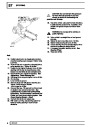
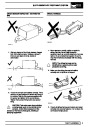
WARNING: Check the integrity of the fuel
system before the inertia switch is reset.
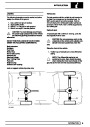
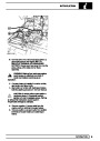
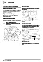
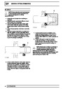
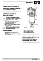
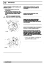
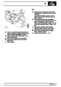
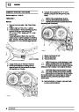
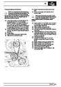
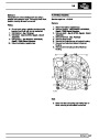
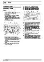
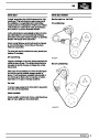
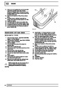
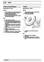
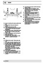
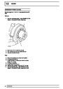
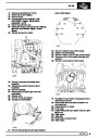
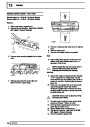
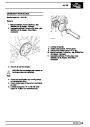
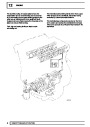
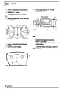
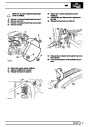
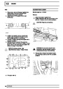
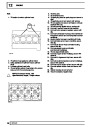
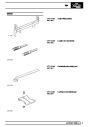
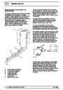
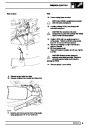
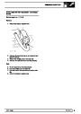
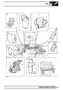
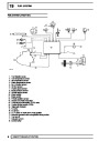
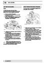
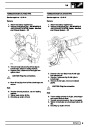
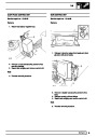
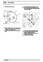
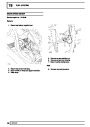
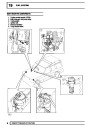
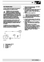
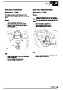
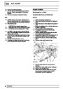
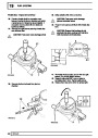
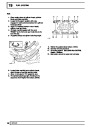
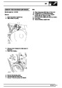
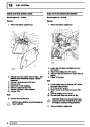
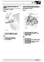
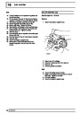
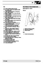
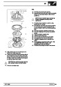
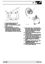
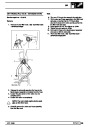
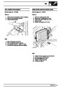
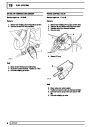
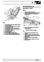
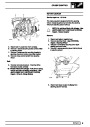
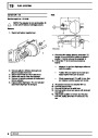
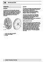
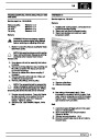
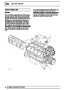
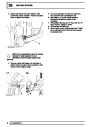
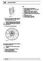
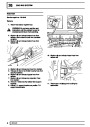
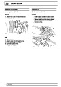
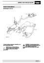
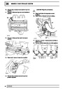
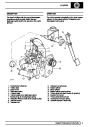
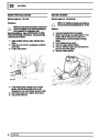
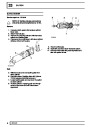
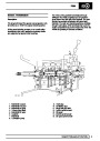
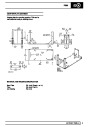
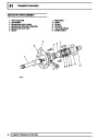
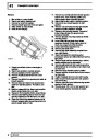
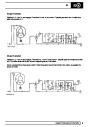
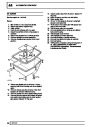
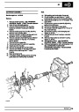
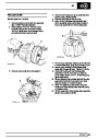
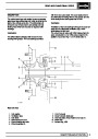
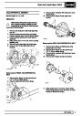
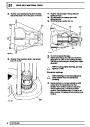
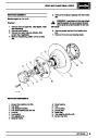
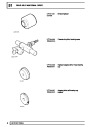
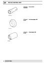
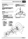
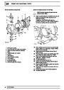
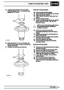
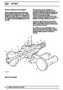
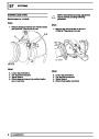
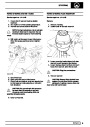
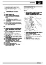
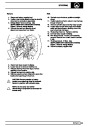
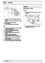
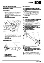
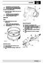
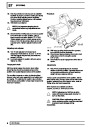
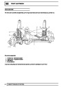
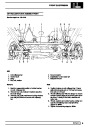
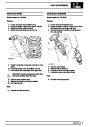
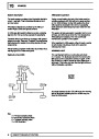
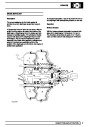
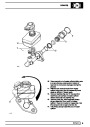
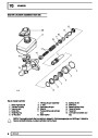
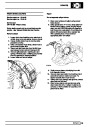
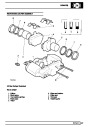
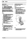
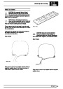
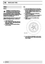
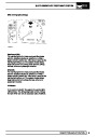
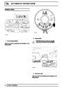
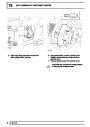
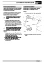
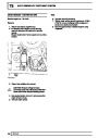
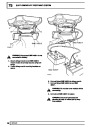
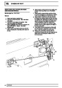
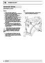
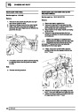
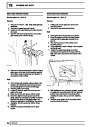
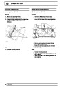
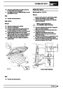
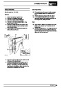
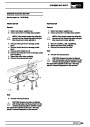
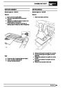
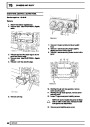
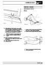
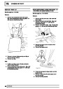
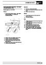
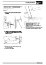
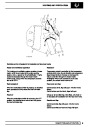
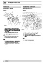
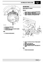
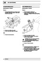
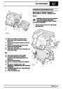
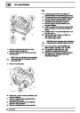
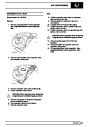
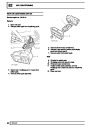
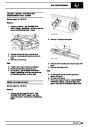
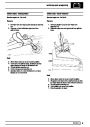
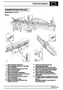
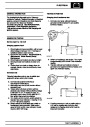
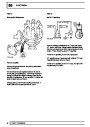
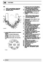
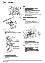
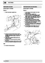
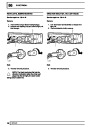
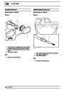
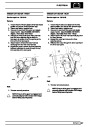
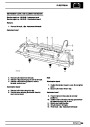
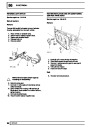
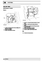
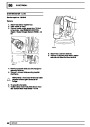
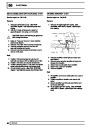
Fuel pressure regulator
The pressure regulator is a mechanical device
controlled by manifold depression and is mounted in
the fuel rail. The regulator ensures that fuel rail
pressure is maintained at a constant pressure
difference to that in the inlet manifold, as manifold
depression increases the regulated fuel pressure is
reduced in direct proportion.
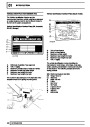
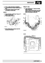
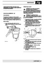
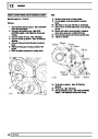
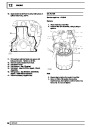
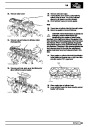
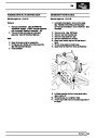
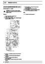
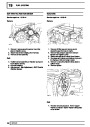
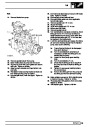
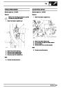
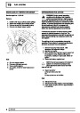
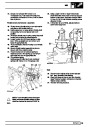
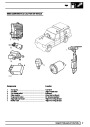
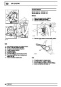
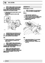
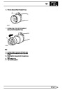
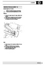
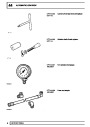
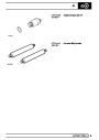
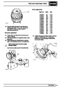
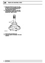
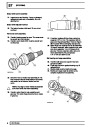
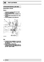
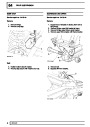
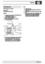
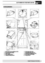
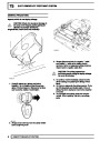
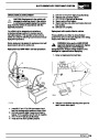
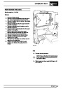
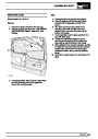
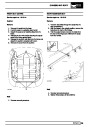
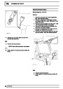
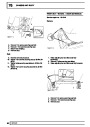
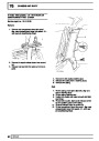
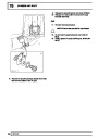
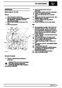
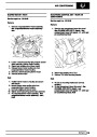
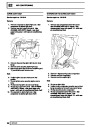
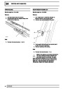
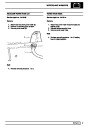
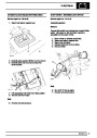
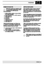
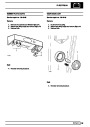
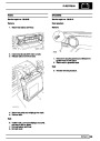
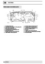
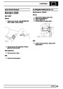
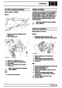
Diagnostic connector
A diagnostic connector is provided to enable
diagnosis to be carried out without disturbing the
system electrical connections and to allow the ECM’s
ability to store certain faults to be utilised.
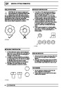
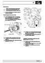
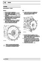
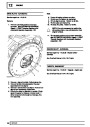
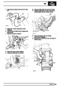
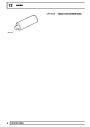
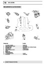
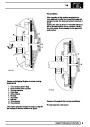
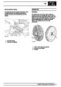
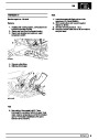
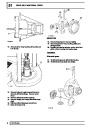
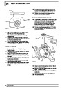
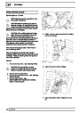
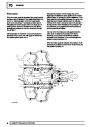
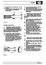
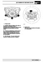
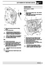
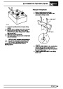
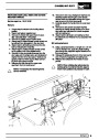
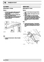
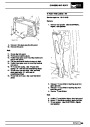
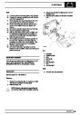
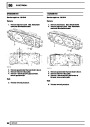
Oxygen sensor - Closed-loop emission control
The MEMS Mpi system operates a closed loop
emission system to ensure the most efficient level of
exhaust gas conversion.
When pressure exceeds the regulator setting excess
fuel is spill returned to the fuel tank swirl pot which
contains the fuel pick-up strainer.
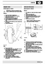
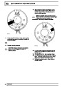
An oxygen sensor fitted in the exhaust manifold
monitors the exhaust gases. It then supplies a small
voltage proportional to exhaust oxygen content to the
ECM As the air/fuel mixture weakens, the exhaust
oxygen content increases and so the voltage to the
ECM decreases. If the mixture becomes richer so the
oxygen content decreases and the voltage increases.
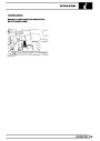
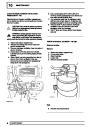
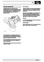
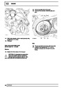
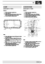
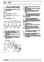
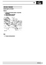
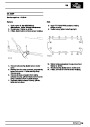
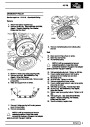
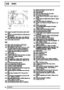
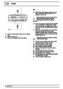
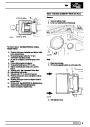
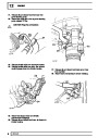
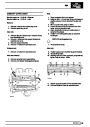
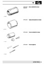
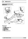
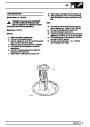
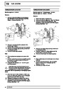
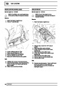
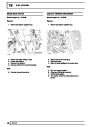
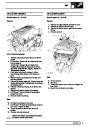
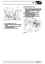
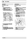
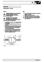
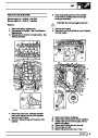
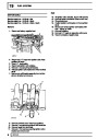
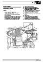
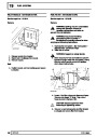
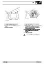
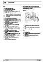
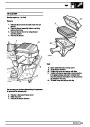
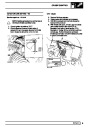
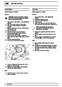
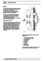
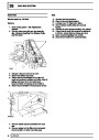
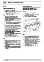
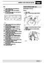
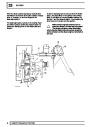
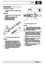
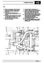
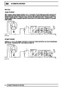
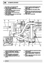
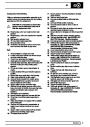
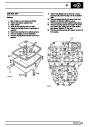
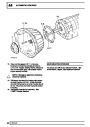
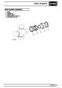
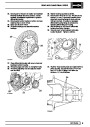
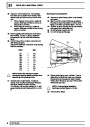
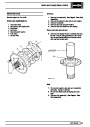
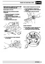
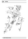
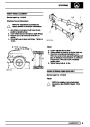
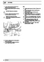
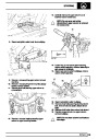
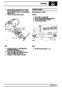
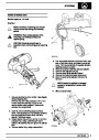
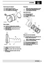
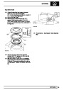
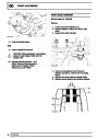
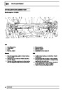
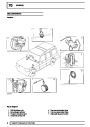
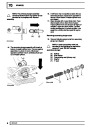
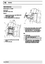
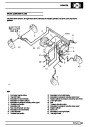
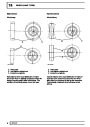
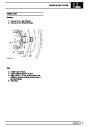
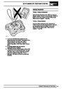
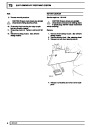
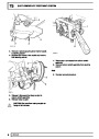
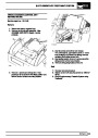
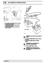
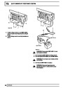
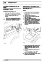
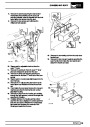
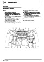
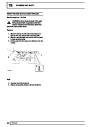
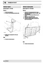
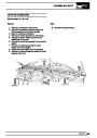
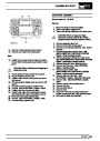
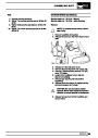
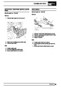
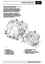
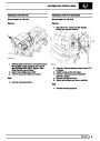
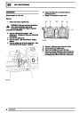
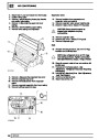
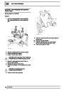
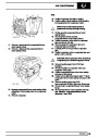
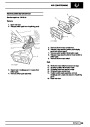
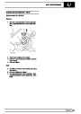
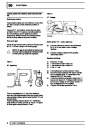
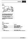
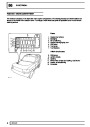
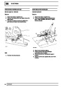
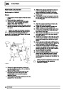
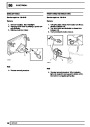
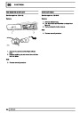
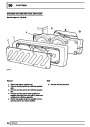
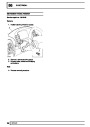
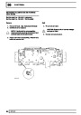
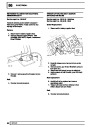
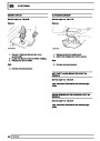
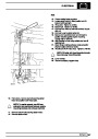
Relay module
The relay module contains the main relay, fuel pump
relay, starter relay and oxygen sensor relay and is
mounted on the ECM mounting bracket.
The main relay is energised when the ignition is
switched on and supplies current to the ECM
The ECM uses this signal voltage to determine the
air/fuel mixture being delivered to the engine, and
adjusts the injector duration to maintain the ratio
necessary for efficient gas conversion by the catalyst.
The fuel pump relay is energised by the ECM for a
short period when the ignition is switched on, during
cranking and while the engine is running.
The starter relay is energised by the cranking signal
from the ignition switch.
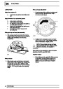
The oxygen sensor has an integral heating element to
ensure an efficient operating temperature is quickly
reached from cold. The electrical supply for the heater
element is controlled by the oxygen sensor relay.
This oxygen sensor relay is energised when the
ignition is switched on and supplies current to the
ECM
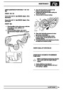
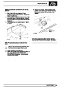
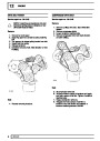
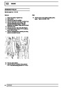
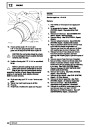
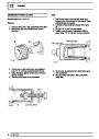
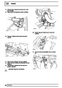
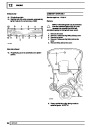
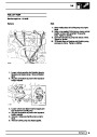
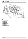
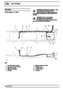
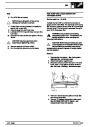
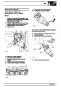
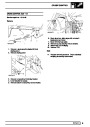
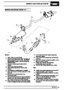
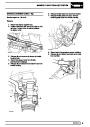
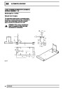
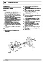
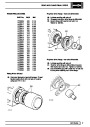
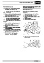
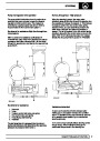
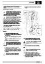
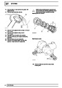
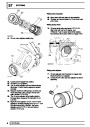
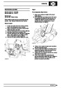
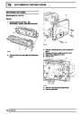
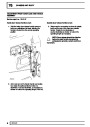
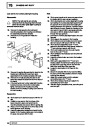
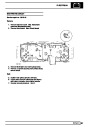
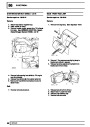
Fuel temperature sensor
The fuel temperature sensor is inserted in the fuel rail
and measures fuel and fuel rail temperatures. During
engine cranking at high temperatures, the ECM
increases fuel supply, and opens the throttle disc via
the stepper motor to aid hot starting.
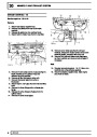
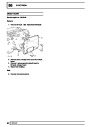
Intake air temperature sensor
The intake air temperature sensor is fitted in the side
of the inlet manifold and sends the ECM a signal
relating to air temperature. The ECM uses this signal
in its calculations on air flow.
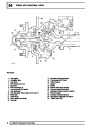
DESCRIPTION AND OPERATION
5
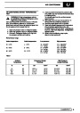
| Categories | Range Rover |
|---|---|
| Tags | Land Rover |
| Model Year | 1998 |
| Download File |
|
| Document Type | Workshop Manual |
| Language | English |
| Product Brand | Land Rover |
| Document File Type | |
| Publisher | landrover.com |
| Wikipedia's Page | http://en.wikipedia.org/wiki/Land_Rover |
| Copyright | Attribution Non-commercial |
(0 votes, average: 0 out of 5)