


19
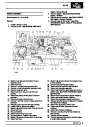
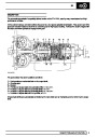
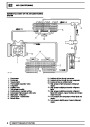
FUEL SYSTEM
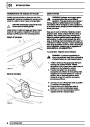
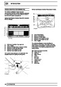
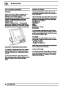
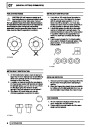
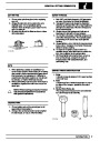
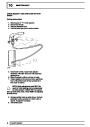
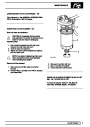
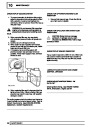
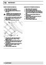
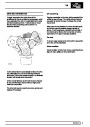
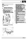
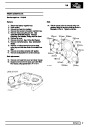
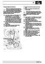
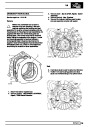
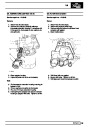
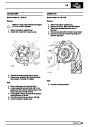
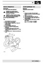
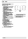
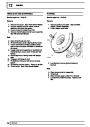
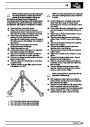
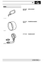
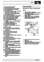
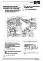
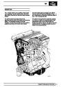
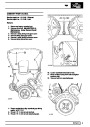
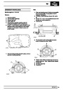
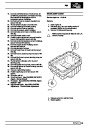
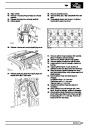
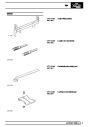
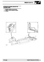
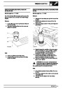
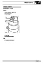
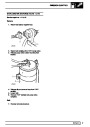
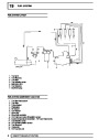
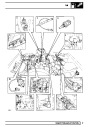
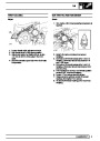
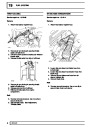
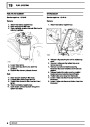
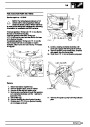
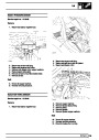
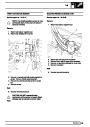
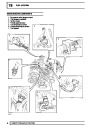
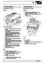
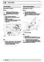
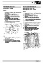
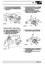
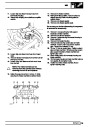
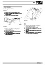
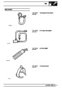
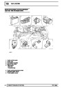
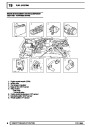
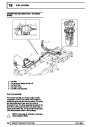
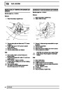
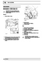
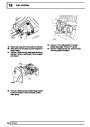
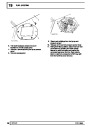
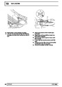
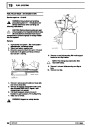
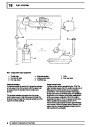
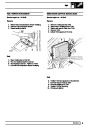
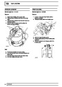
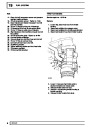
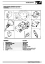
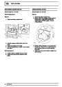
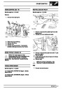
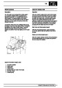
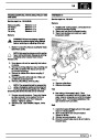
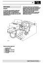
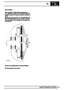
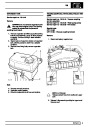
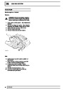
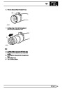
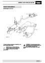
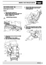
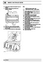
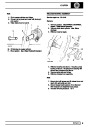
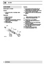
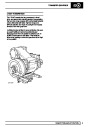
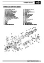
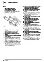
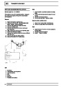
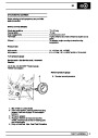
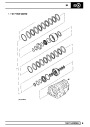
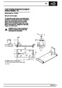
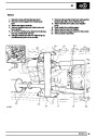
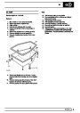
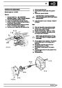
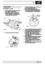
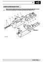
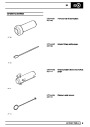
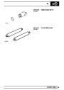
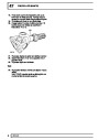
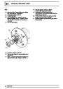
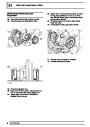
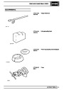
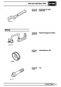
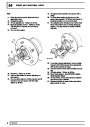
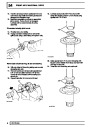
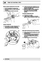
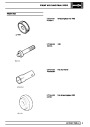
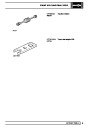
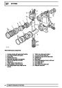
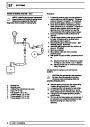
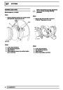
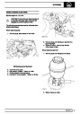
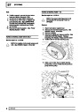
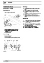
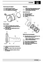
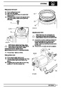
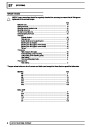
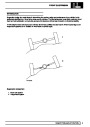
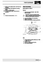
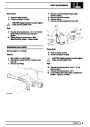
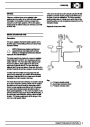
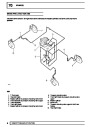
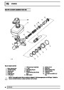
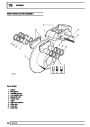
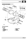
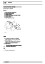
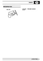
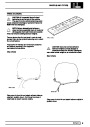
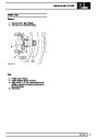
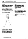
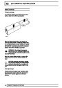
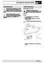
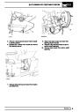
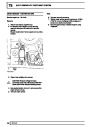
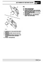
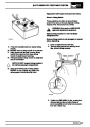
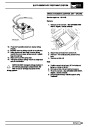
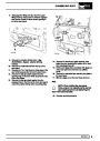
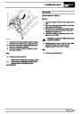
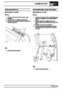
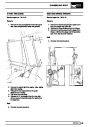
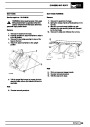
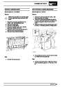
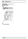
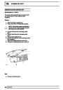
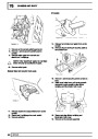
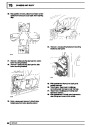
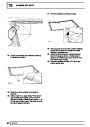
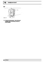
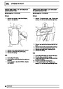
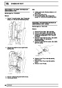
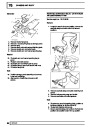
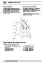
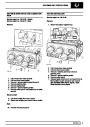
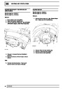
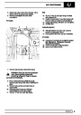
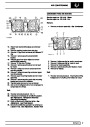
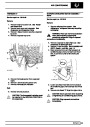
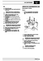
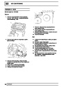
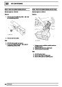
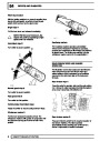
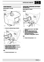
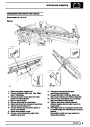
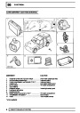
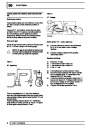
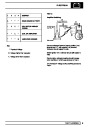
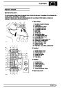
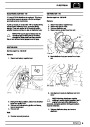
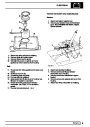
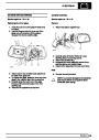
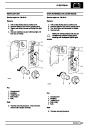
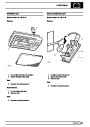
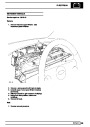
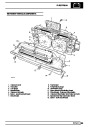
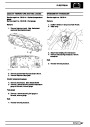
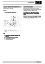
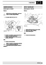
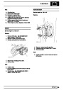
Injectors
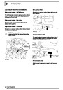
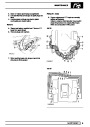
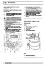
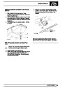
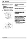
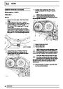
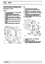
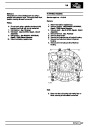
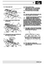
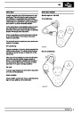
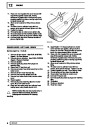
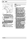
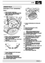
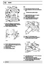
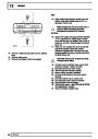
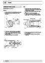
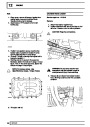
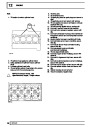
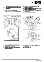
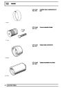
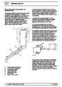
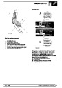
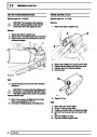
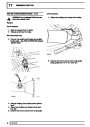
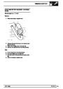
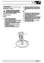
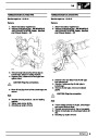
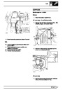
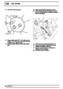
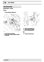
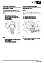
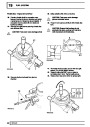
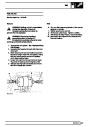
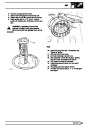
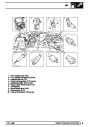
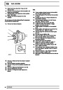
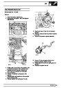
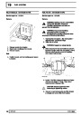
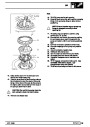
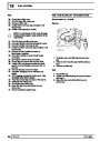
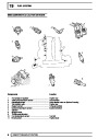
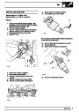
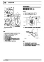
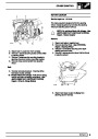
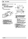
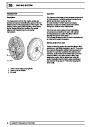
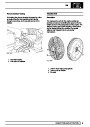
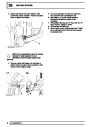
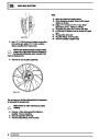
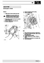
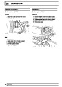
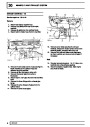
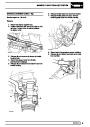
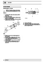
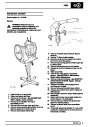
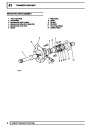
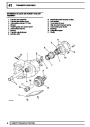
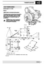
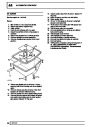
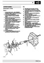
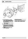
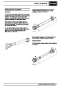
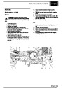
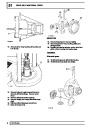
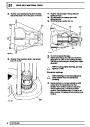
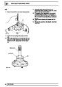
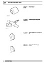
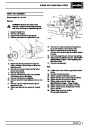
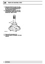
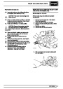
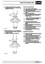
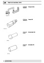
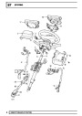
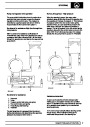
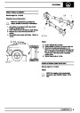
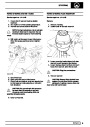
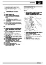
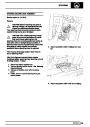
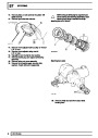
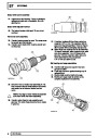
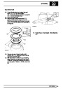
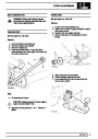
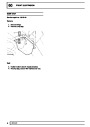
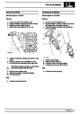
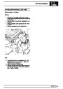
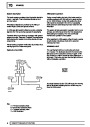
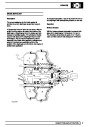
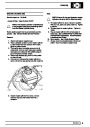
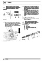
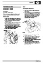
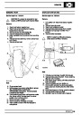
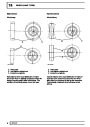
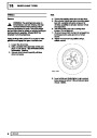
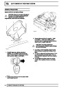
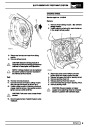
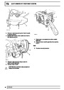
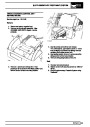
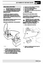
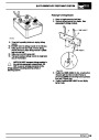
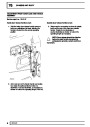
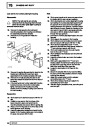
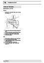
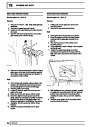
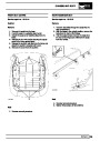
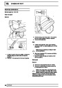
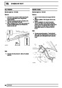
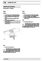
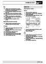
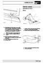
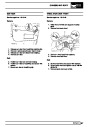
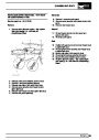
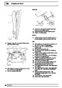
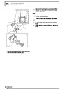
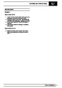
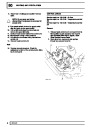
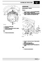
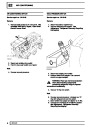
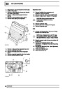
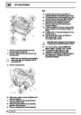
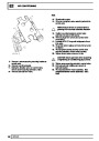
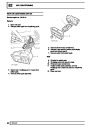
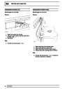
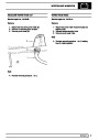
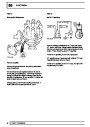
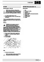
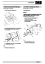
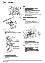
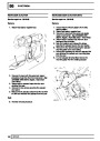
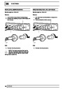
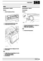
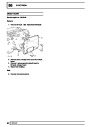
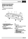
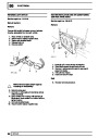
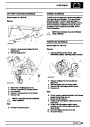
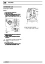
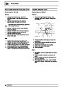
Stepper motor
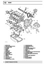
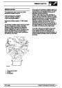
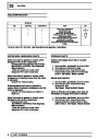
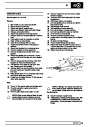
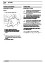
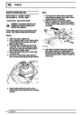
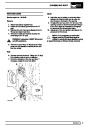
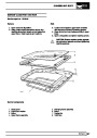
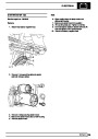
The four fuel injectors are fitted between the
pressurised fuel rail and inlet manifold. Each injector
comprises of a solenoid operated needle valve and a
specially designed nozzle to ensure good fuel
atomisation.
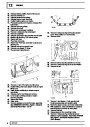
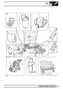
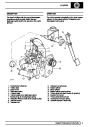
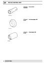
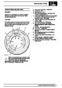
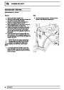
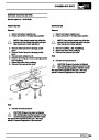
The stepper motor is contained within the throttle
housing and operates a cam and push rod via a
reduction gear. The push rod is in direct contact with
the throttle lever and moves the throttle disc to control
idle and fast idle speed. The stepper motor maximum
movement is 3.75 revolutions accomplished in steps
of 7.5°. The reduction gear converts this into 180°of
cam movement.
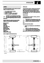
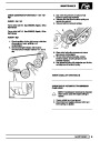
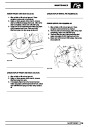
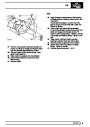
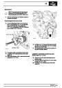
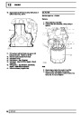
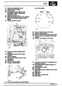
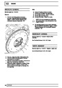
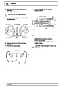
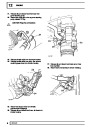
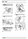
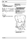
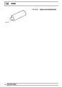
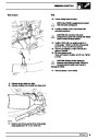
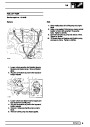
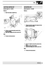
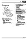
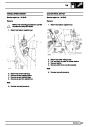
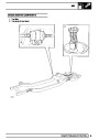
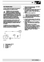
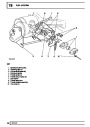
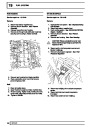
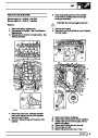
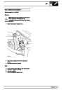
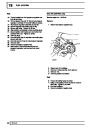
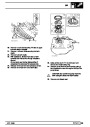
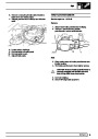
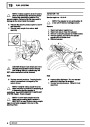
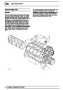
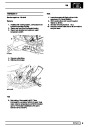
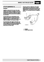
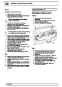
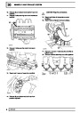
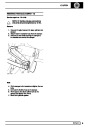
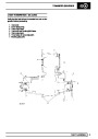
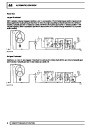
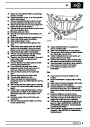
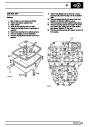
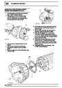
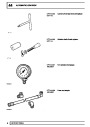
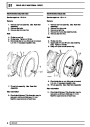
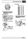
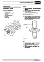
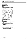
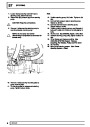
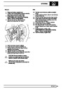
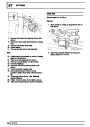
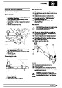
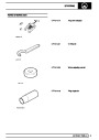
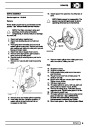
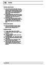
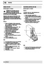
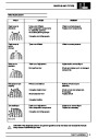
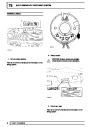
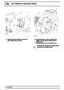
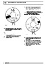
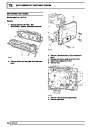
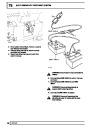
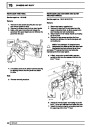
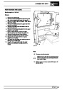
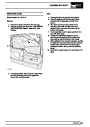
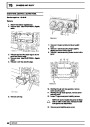
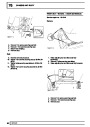
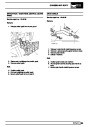
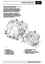
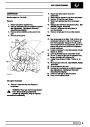
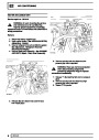
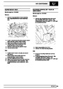
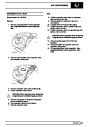
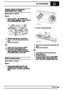
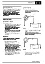
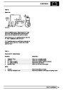
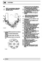
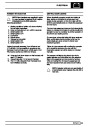
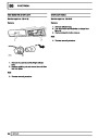
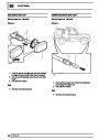
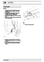
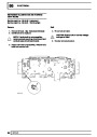
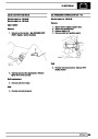
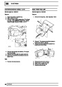
Engine coolant temperature sensor
The coolant temperature sensor is mounted in the
thermostat housing and is immersed in the engine
coolant. The sensor is a resistive device in which the
resistance varies with temperature
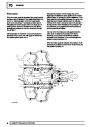
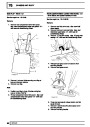
The throttle lever has a throttle position setting screw
which rests on the stepper motor operating pin when
the throttle pedal is released and is used to set the
relationship between engine speed and stepper motor
position.
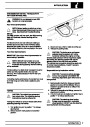
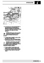
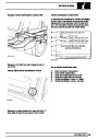
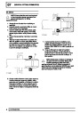
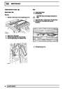
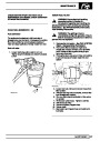
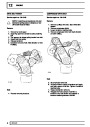
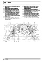
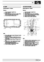
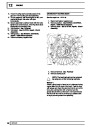
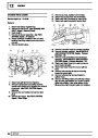
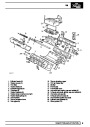
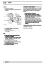
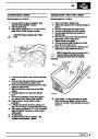
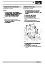
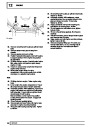
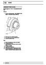
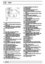
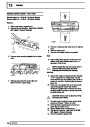
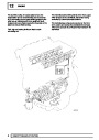
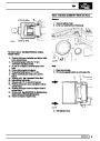
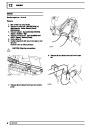
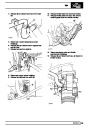
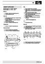
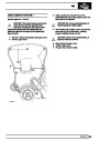
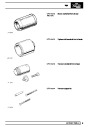
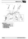
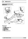
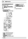
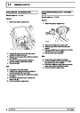
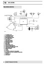
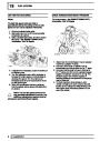
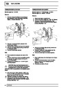
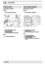
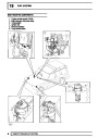
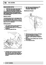
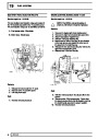
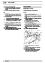
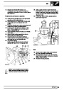
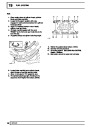
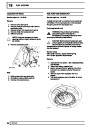
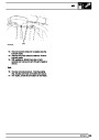
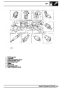
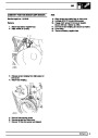
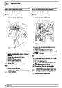
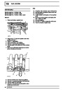
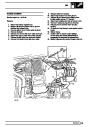
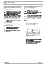
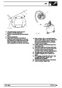
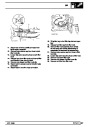
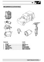
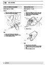
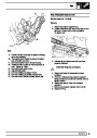
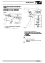
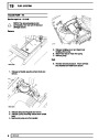
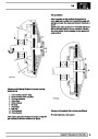
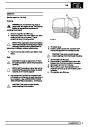
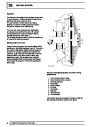
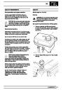
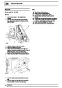
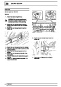
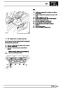
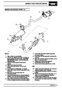
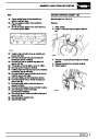
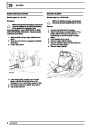
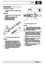
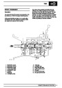
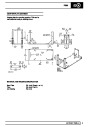
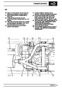
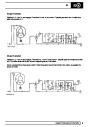
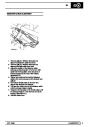
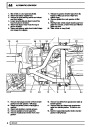
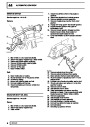
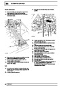
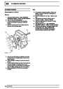
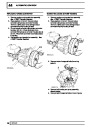
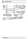
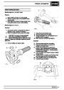
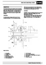
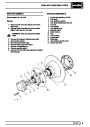
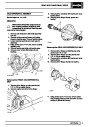
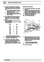
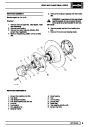
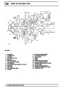
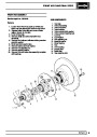
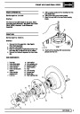
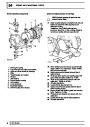
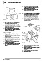
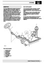
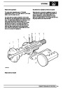
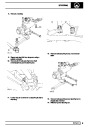
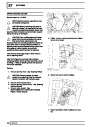
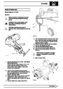
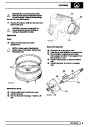
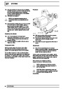
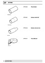
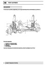
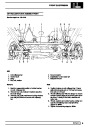
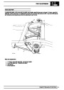
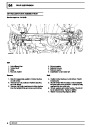
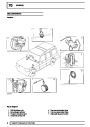
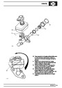
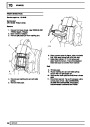
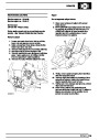
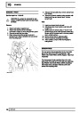
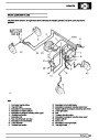
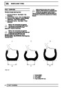
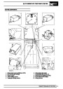
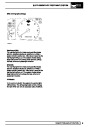
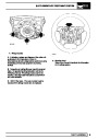
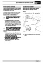
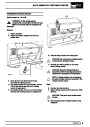
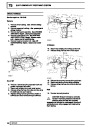
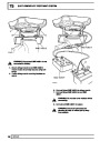
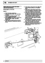
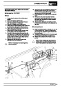
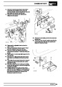
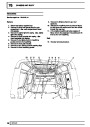
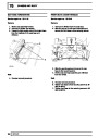
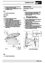
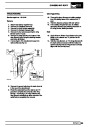
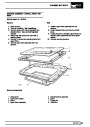
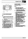
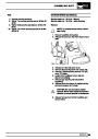
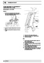
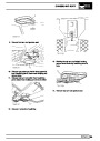
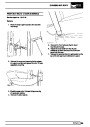
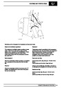
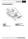
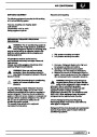
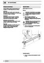
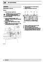
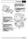
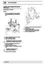
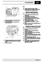
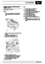
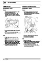
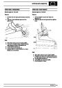
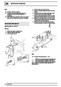
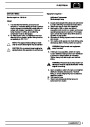
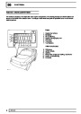
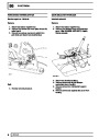
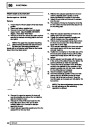
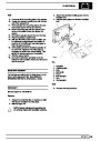
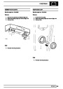
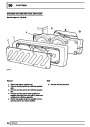
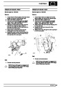
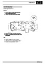
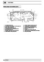
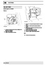
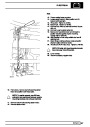
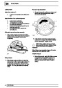
Throttle housing
The throttle housing is attached to the inlet manifold
via a rubber sandwich plate and incorporates a throttle
disc which is connected to the throttle pedal via the
throttle lever and a cable.
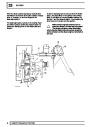
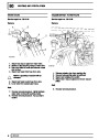
In the side of the throttle housing is a throttle air
bypass bleed screw to provide easier and more
sensitive setting of the stepper motor position at idle.
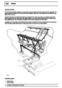
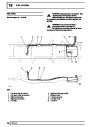
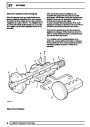
There are two breather pipes; one either side of the
throttle disc. When the engine is running with the
throttle disc open, both pipes are subject to manifold
depression and draw crankcase fumes into the
manifold. When the throttle disc is closed, only the
pipe on the inlet manifold side of the disc is subject to
manifold depression. This pipe incorporates a
restrictor to prevent engine oil being drawn into the
engine by the substantially greater manifold
depression.
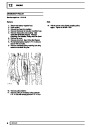
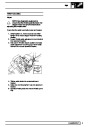
The stepper motor position is checked using Testbook
and should be within the range of 20 to 40 steps when
the engine is run in. If it is identified as being outside
this range it can be adjusted to within range by turning
the throttle air bypass bleed screw. It is important to
follow Testbook setting procedure when adjusting this
screw to prevent mismatching of throttle body
settings. This ensures that the stepper motor is at the
optimum position within its range for providing further
movement to compensate for changes in engine load
or temperature in accordance with signals from the
ECM
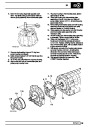
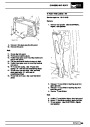
Also incorporated in the throttle housing are the
throttle potentiometer and stepper motor.
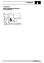
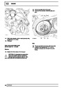
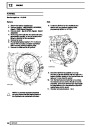
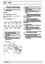
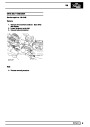
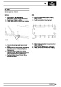
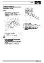
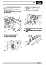
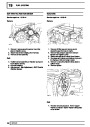
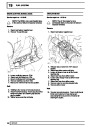
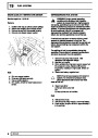
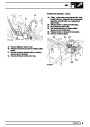
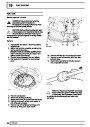
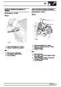
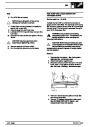
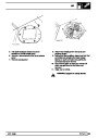
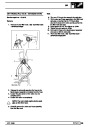
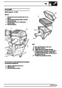
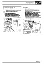
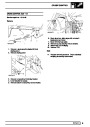
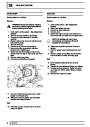
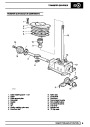
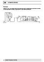
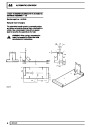
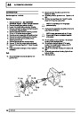
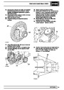
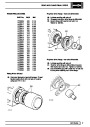
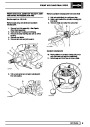
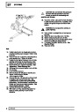
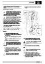
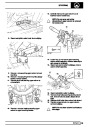
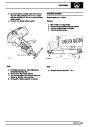
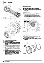
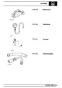
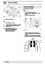
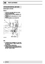
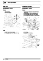
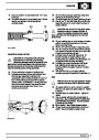
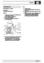
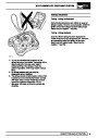
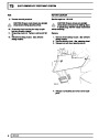
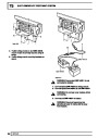
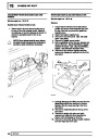
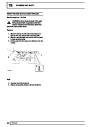
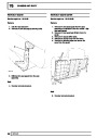
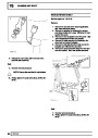
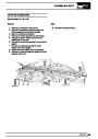
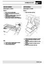
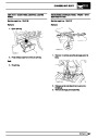
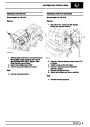
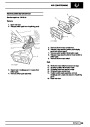
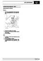
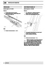
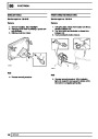
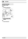
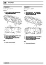
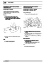
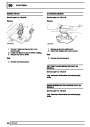
Throttle potentiometer
NOTE: The stepper motor and throttle
position setting screws must only be
adjusted when Testbook identifies the
requirement.
The throttle potentiometer is mounted in front of the
throttle housing and is directly coupled to the throttle
disc shaft.
Three wires connect the throttle potentiometer to the
ECM; a 5 volt supply to the potentiometer, an earth
return to the ECM and an output voltage to the ECM
which indicates the rate of throttle disc movement.
4
DESCRIPTION AND OPERATION
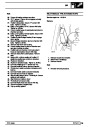
| Categories | Range Rover |
|---|---|
| Tags | Land Rover |
| Model Year | 1998 |
| Download File |
|
| Document Type | Workshop Manual |
| Language | English |
| Product Brand | Land Rover |
| Document File Type | |
| Publisher | landrover.com |
| Wikipedia's Page | http://en.wikipedia.org/wiki/Land_Rover |
| Copyright | Attribution Non-commercial |
(0 votes, average: 0 out of 5)