


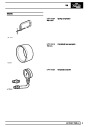
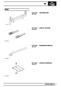
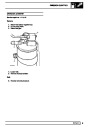


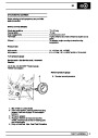


ELECTRICAL
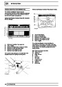
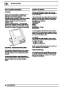
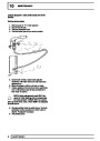
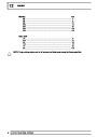
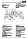
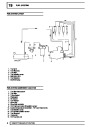
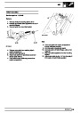
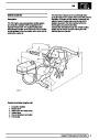
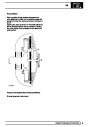
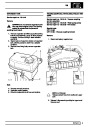
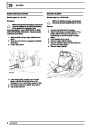
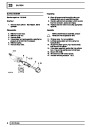
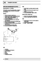
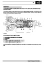
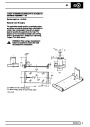
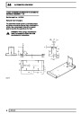
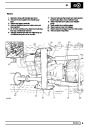
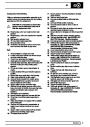
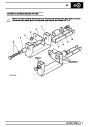
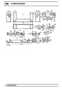
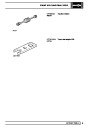
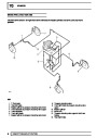
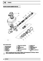
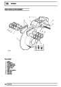
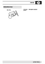
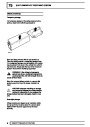
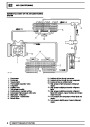
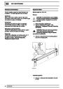
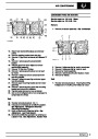
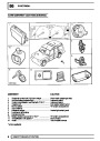
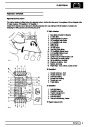
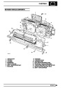
MAIN PRINTED CIRCUIT
Service repair no - 88.20.19
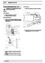
Remove
1.
2.
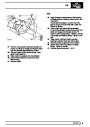
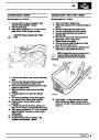
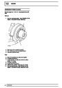
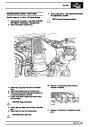
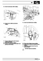
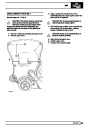
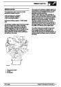
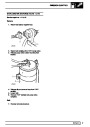
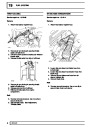
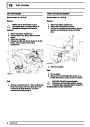
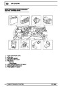
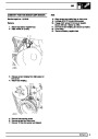
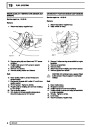
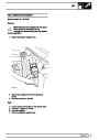
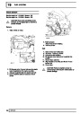
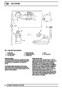
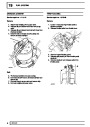
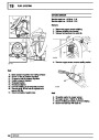
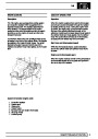
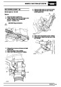
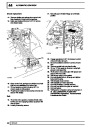
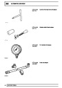
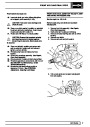
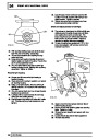
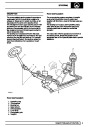
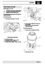
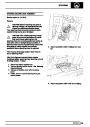
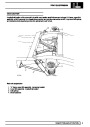
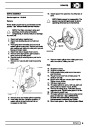
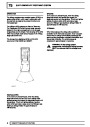
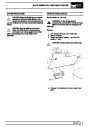
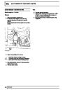
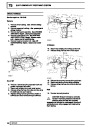
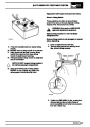
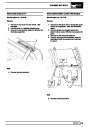
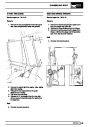
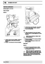
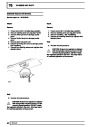
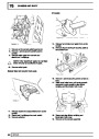
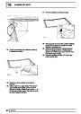
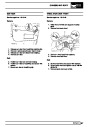
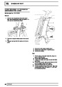
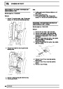
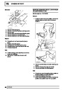
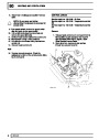
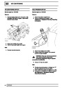
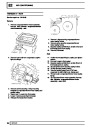
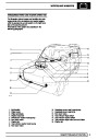
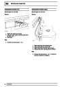
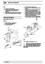
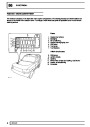
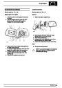
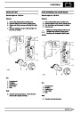
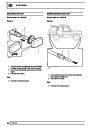
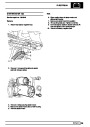
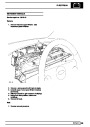
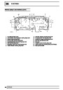
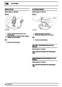
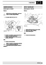
Remove instrument cowl. See Instrument
cowl and illumination board
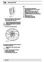
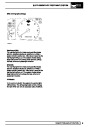
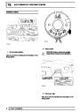
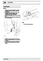
Remove circuit board. See Circuit board
3.
4.
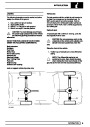
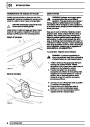
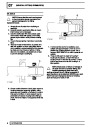
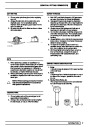
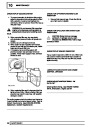
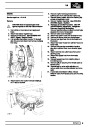
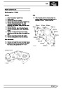
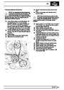
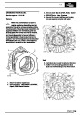
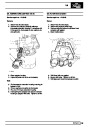
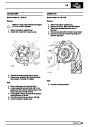
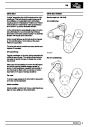
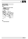
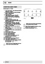
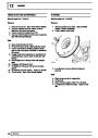
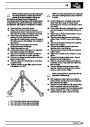
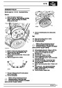
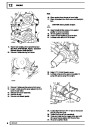
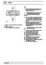
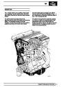
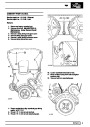
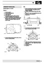
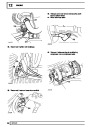
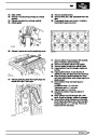
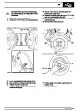
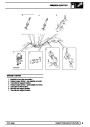
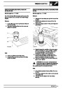
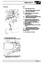
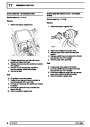
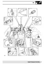
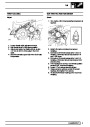
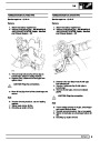
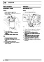
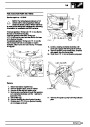
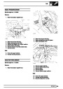
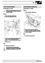
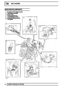
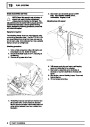
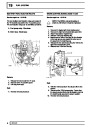
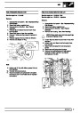
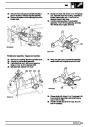
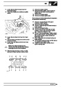
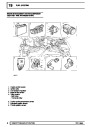
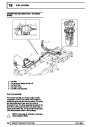
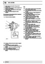
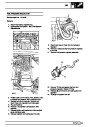
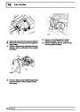
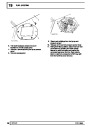
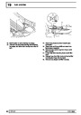
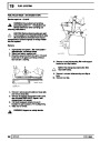
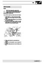
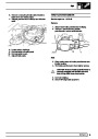
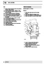
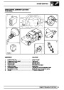
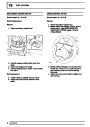
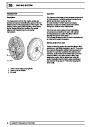
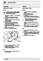
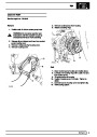
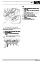
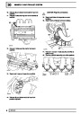
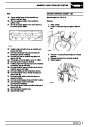
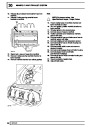
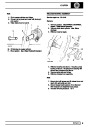
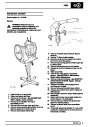
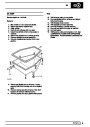
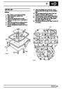
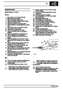
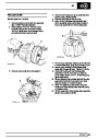
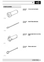
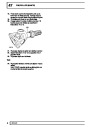
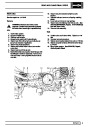
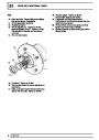
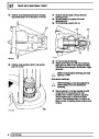
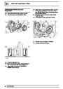
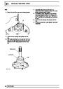
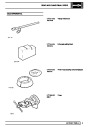
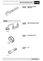
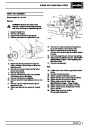
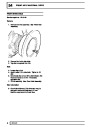
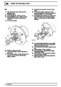
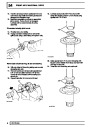
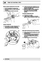
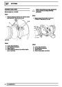
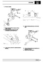
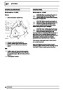
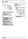
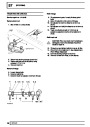
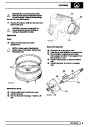
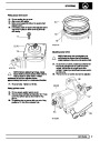
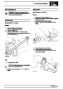
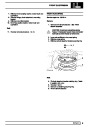
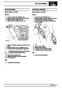
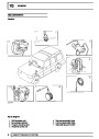
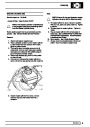
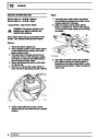
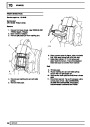
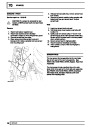
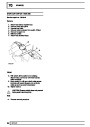
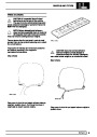
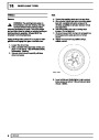
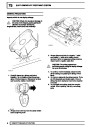
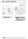
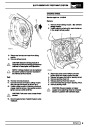
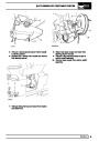
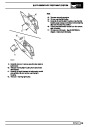
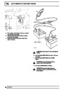
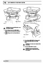
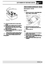
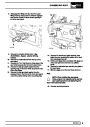
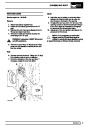
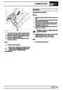
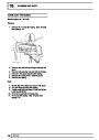
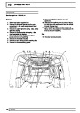
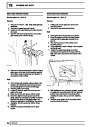
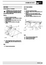
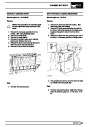
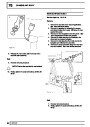
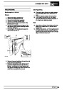
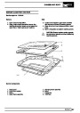
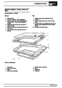
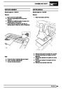
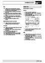
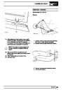
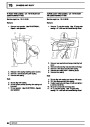
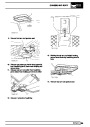
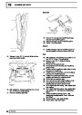
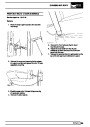
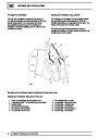
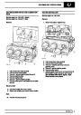
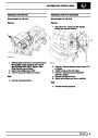
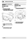
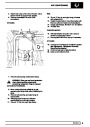
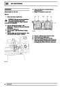
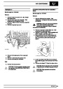
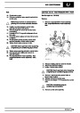
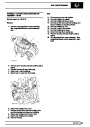
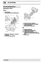
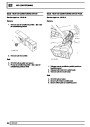
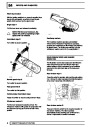
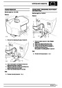
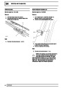
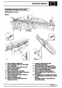
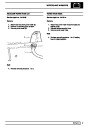
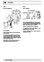
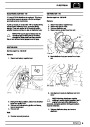
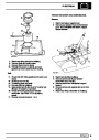
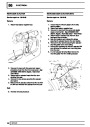
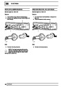
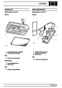
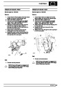
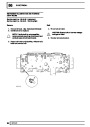
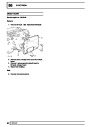
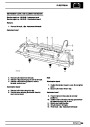
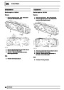
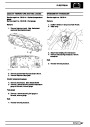
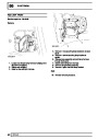
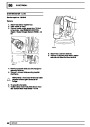
Remove illumination and warning lamp bulbs.
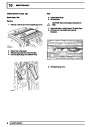
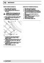
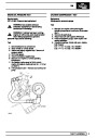
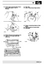
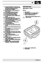
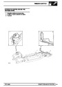
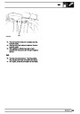
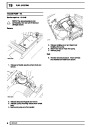
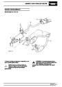
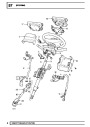
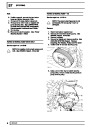
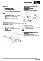
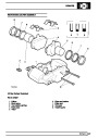
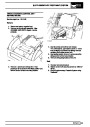
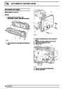
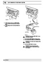
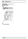
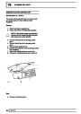
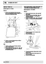
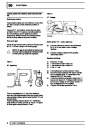
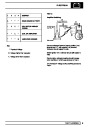
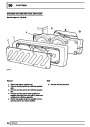
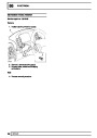
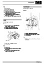
Remove 13 screws securing main printed circuit,
remove circuit.
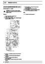
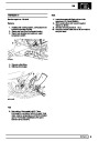
Refit
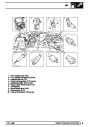
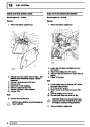
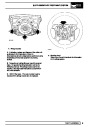
5.
6.
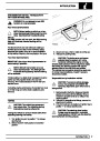
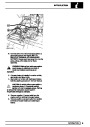
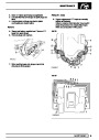
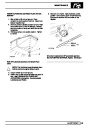
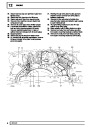
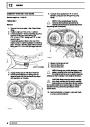
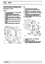
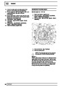
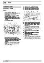
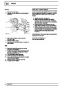
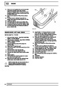
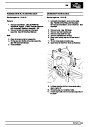
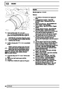
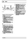
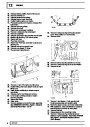
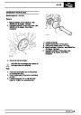
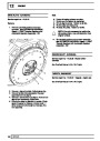
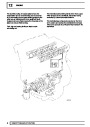
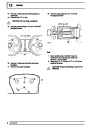
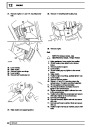
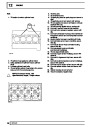
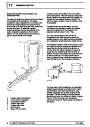
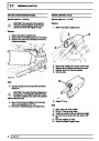
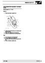
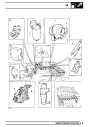
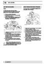
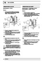
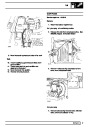
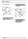
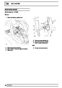
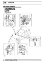
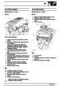
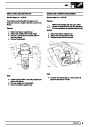
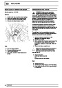
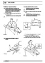
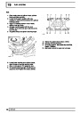
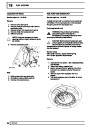
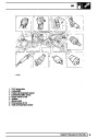
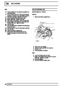
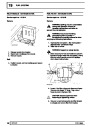
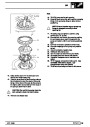
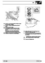
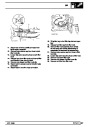
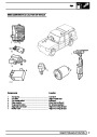
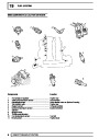
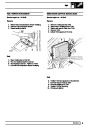
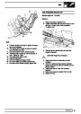
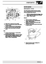
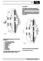
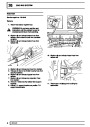
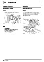
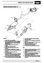
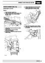
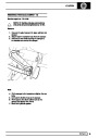
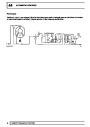
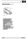
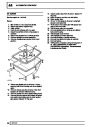
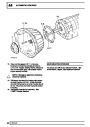
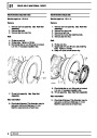
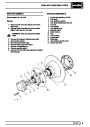
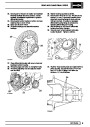
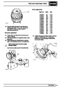
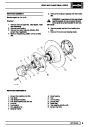
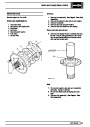
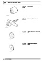
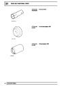
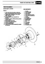
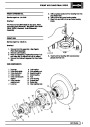
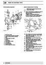
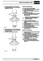
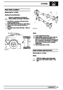
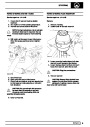
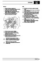
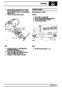
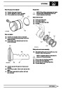
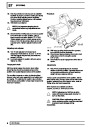
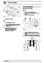
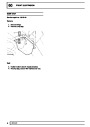
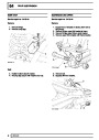
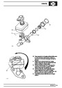
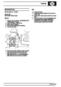
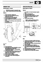
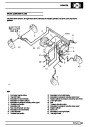
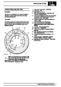
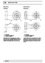
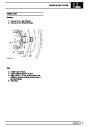
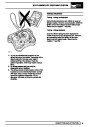
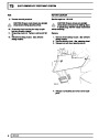
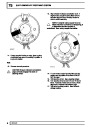
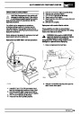
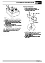
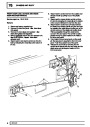
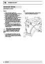
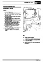
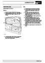
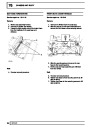
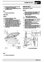
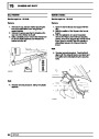
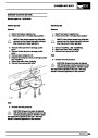
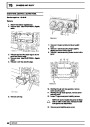
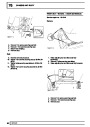
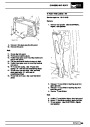
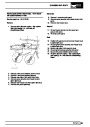
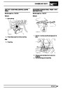
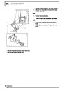
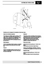
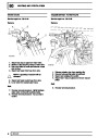
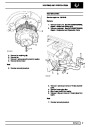
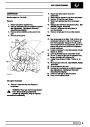
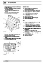
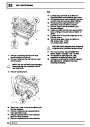
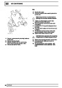
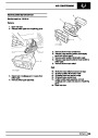
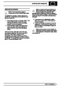
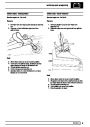
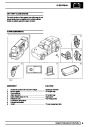
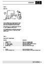
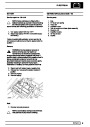
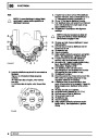
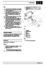
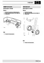
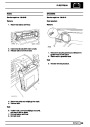
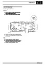
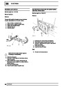
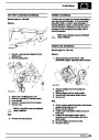
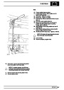
Position main printed circuit to binnacle.
Ensure screw holes in instruments are aligned
with holes in binnacle, fit and tighten screws.
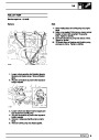
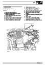
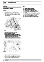
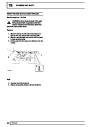
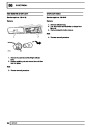
Reverse removal procedure. 1 and 2.
7.
REPAIR
31
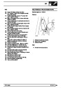
| Categories | Range Rover |
|---|---|
| Tags | Land Rover |
| Model Year | 1998 |
| Download File |
|
| Document Type | Workshop Manual |
| Language | English |
| Product Brand | Land Rover |
| Document File Type | |
| Publisher | landrover.com |
| Wikipedia's Page | http://en.wikipedia.org/wiki/Land_Rover |
| Copyright | Attribution Non-commercial |
(0 votes, average: 0 out of 5)