


51
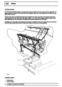
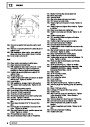
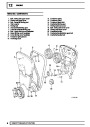
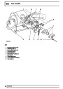
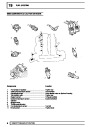
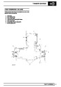
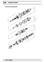
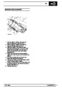
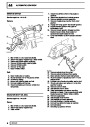
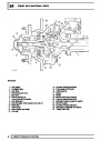
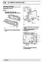
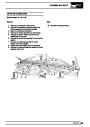
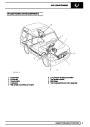
REAR AXLE AND FINAL DRIVE
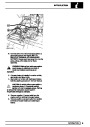
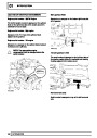
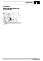
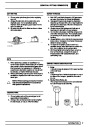
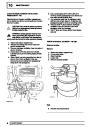
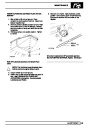
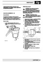
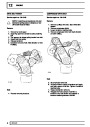
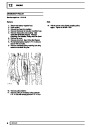
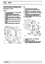
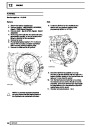
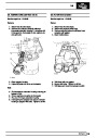
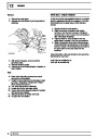
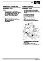
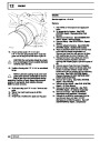
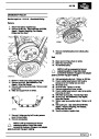
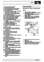
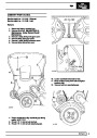
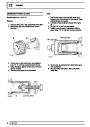
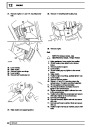
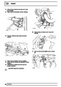
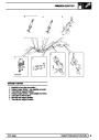
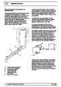
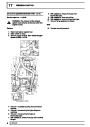
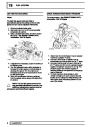
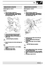
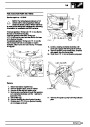
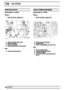
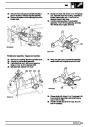
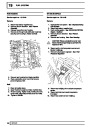
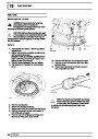
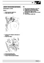
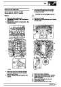
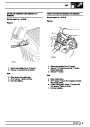
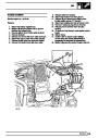
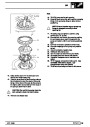
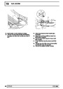
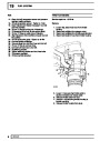
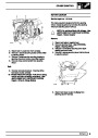
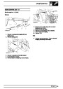
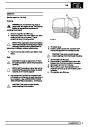
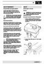
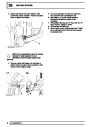
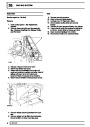
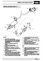
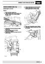
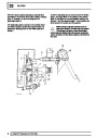
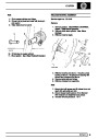
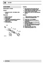
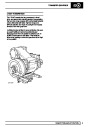
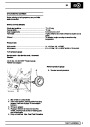
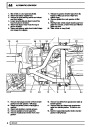
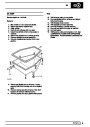
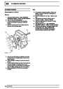
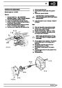
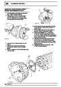
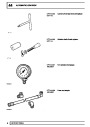
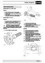
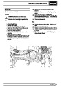
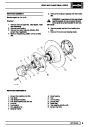
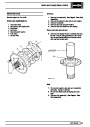
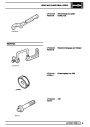
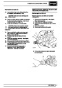
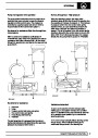
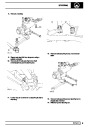
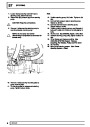
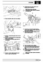
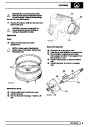
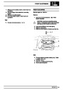
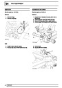
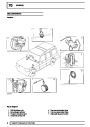
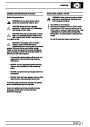
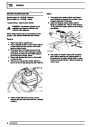
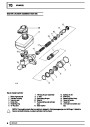
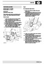
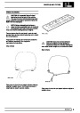
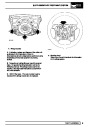
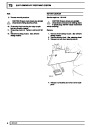
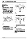
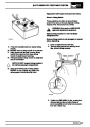
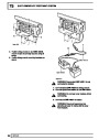
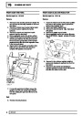
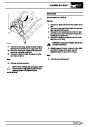
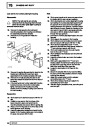
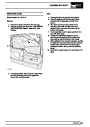
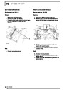
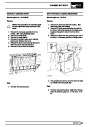
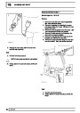
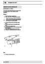
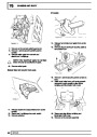
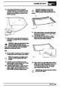
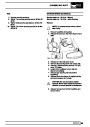
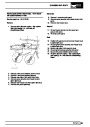
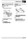
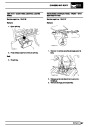
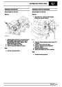
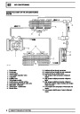
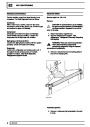
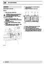
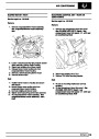
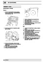
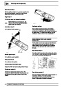
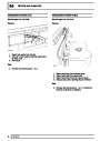
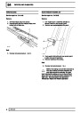
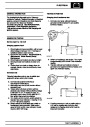
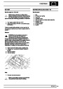
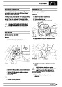
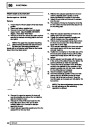
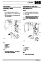
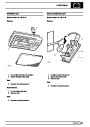
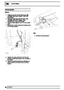
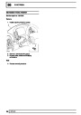
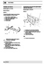
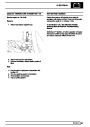
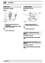
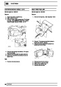
35.
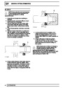
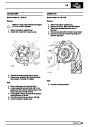
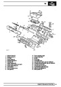
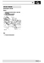
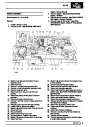
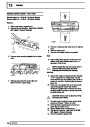
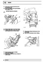
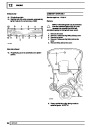
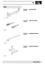
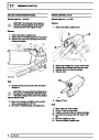
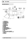
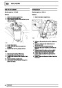
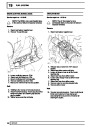
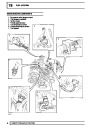
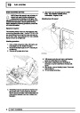
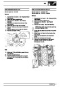
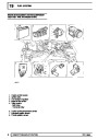
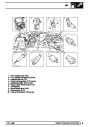
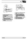
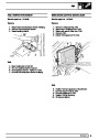
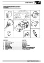
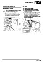
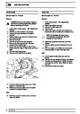
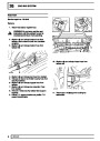
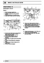
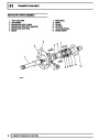
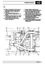
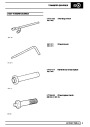
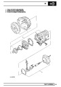
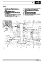
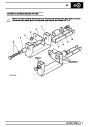
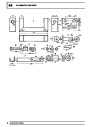
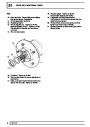
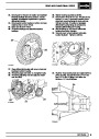
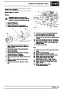
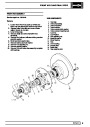
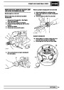
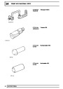
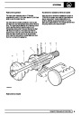
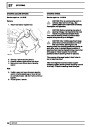
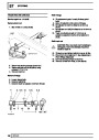
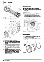
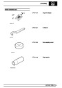
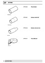
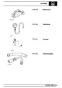
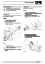
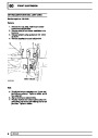
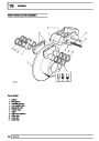
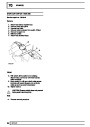
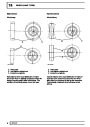
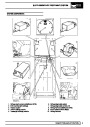
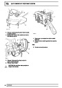
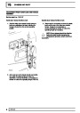
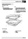
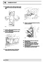
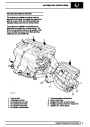
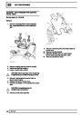
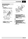
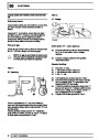
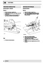
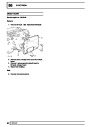
Fit pinion outer bearing track to pinion housing.
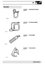
Use service tools LRT-54-505 and LRT-54-507.
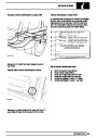
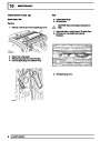
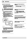
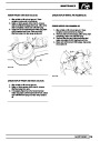
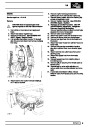
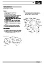
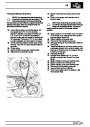
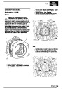
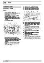
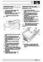
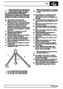
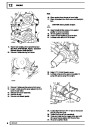
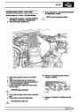
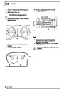
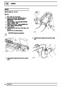
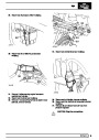
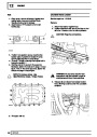
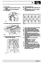
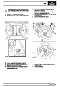
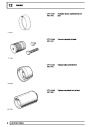
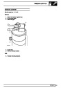
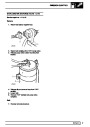
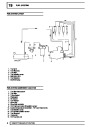
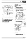
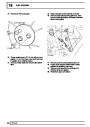
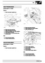
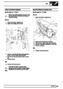
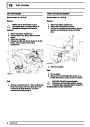
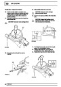
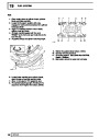
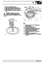
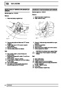
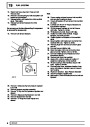
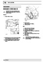
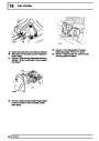
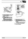
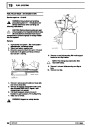
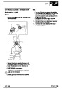
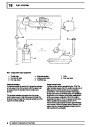
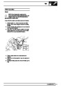
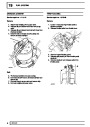
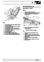
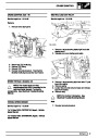
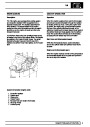
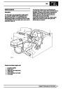
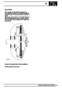
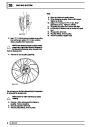
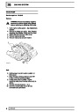
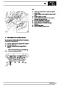
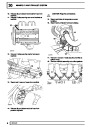
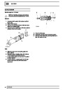
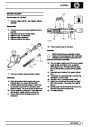
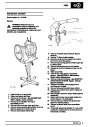
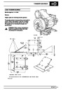
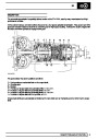
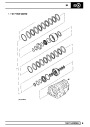
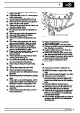
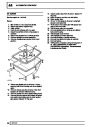
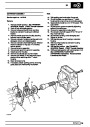
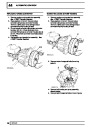
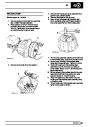
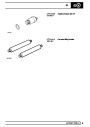
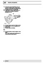
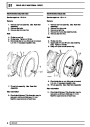
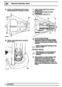
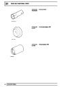
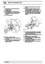
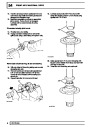
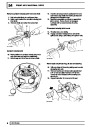
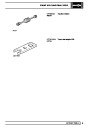
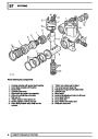
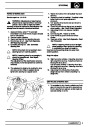
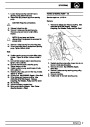
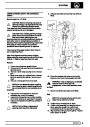
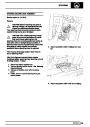
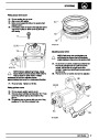
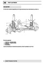
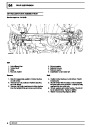
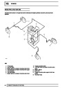
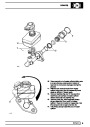
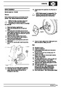
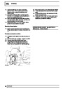
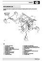
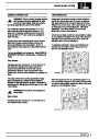
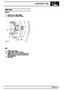
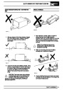
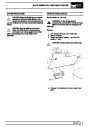
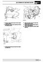
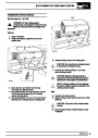
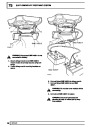
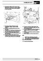
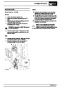
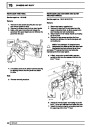
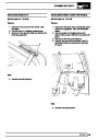
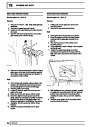
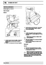
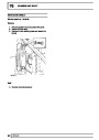
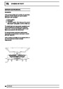
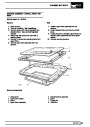
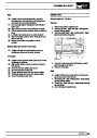
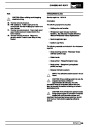
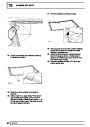
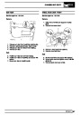
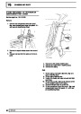
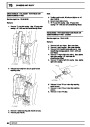
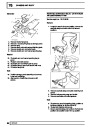
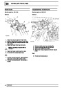
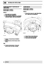
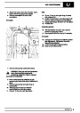
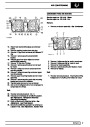
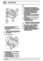
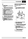
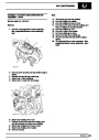
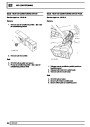
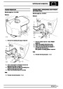
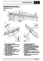
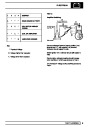
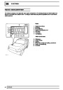
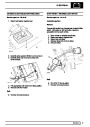
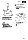
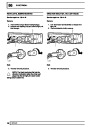
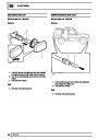
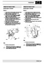
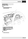
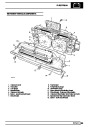
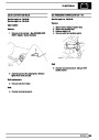
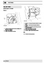
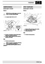
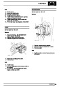
37. Fit pinion into its location without shims for
bearing pre-load.
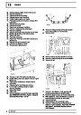
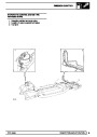
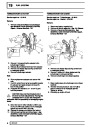
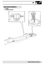
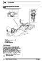
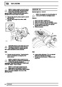
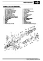
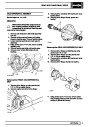
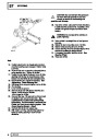
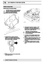
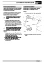
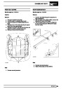
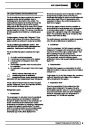
38.
39.
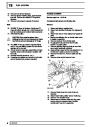
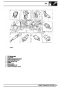
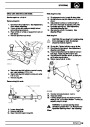
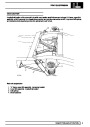
Fit outer bearing, and spacer (front axle
differential only).
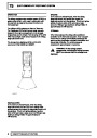
Fit driving flange, washer and nut.
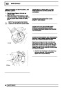
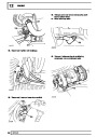
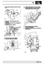
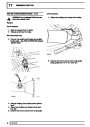
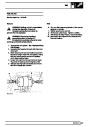
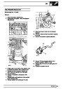
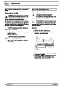
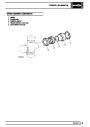
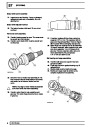
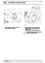
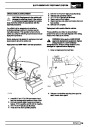
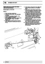
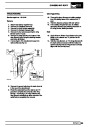
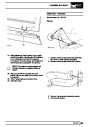
40.
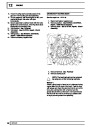
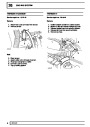
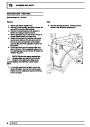
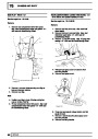
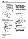
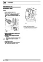
41.
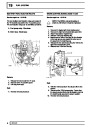
Do not fit oil seal at this stage.
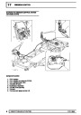
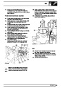
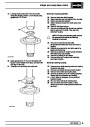
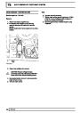
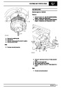
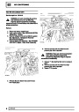
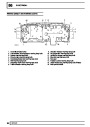
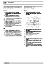
Tighten pinion flange nut until force required to
rotate pinion is 3 Nm if new bearings are fitted.
This will pre-load bearings to check pinion height
dimension.
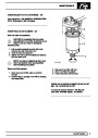
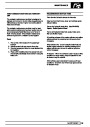
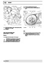
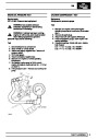
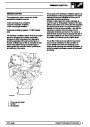
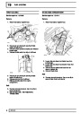
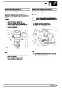
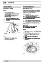
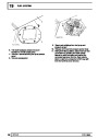
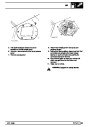
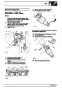
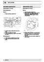
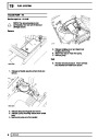
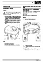
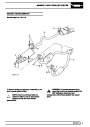
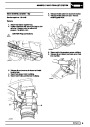
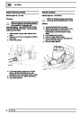
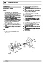
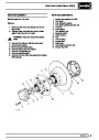
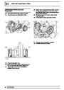
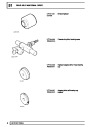
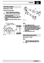
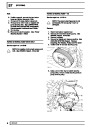
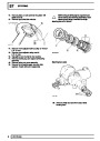
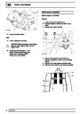
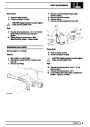
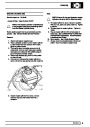
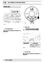
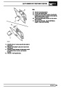
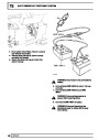
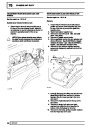
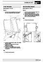
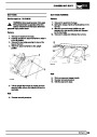
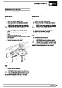
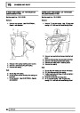
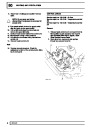
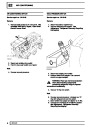
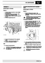
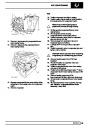
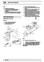
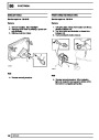
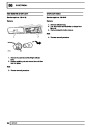
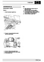
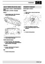
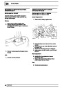
36.
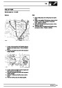
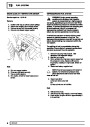
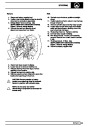
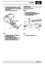
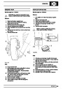
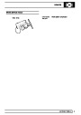
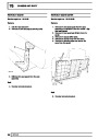
Fit pinion head bearing to pinion. Use service
tool LRT-54-502.
NOTE: If using original bearings, pre-load
figure is 1.5 Nm.
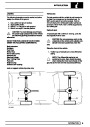
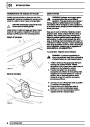
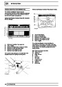
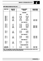
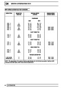
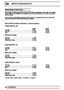
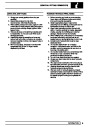
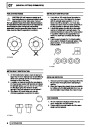
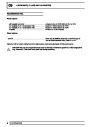
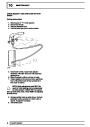
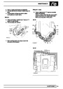
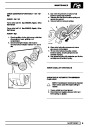
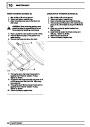
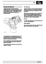
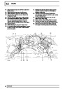
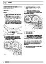
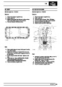
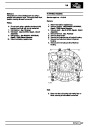
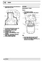
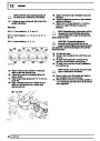
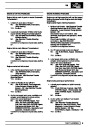
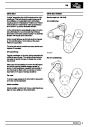
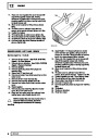
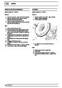
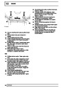
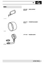
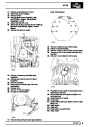
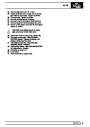
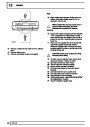
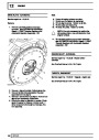
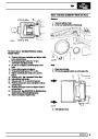
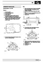
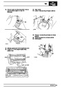
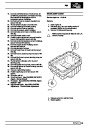
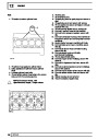
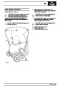
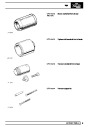
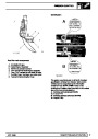
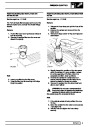
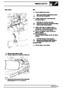
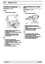
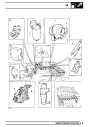
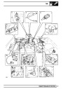
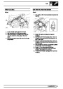
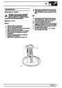
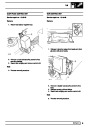
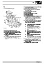
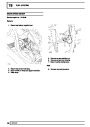
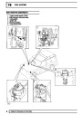
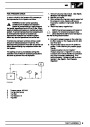
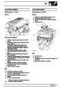
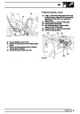
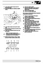
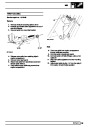
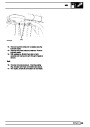
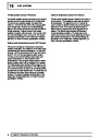
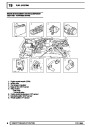
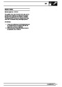
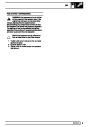
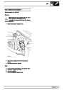
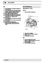
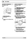
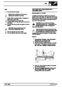
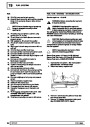
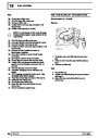
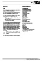
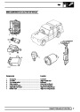
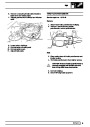
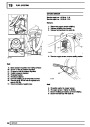
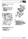
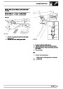
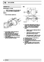
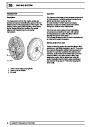
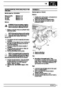
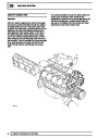
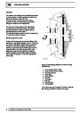
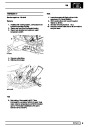
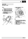
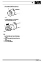
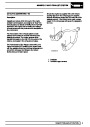
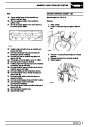
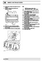
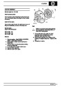
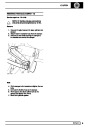
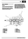
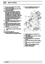
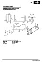
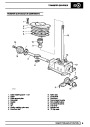
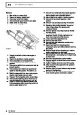
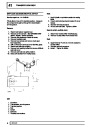
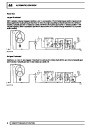
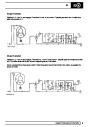
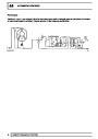
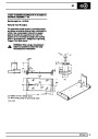
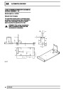
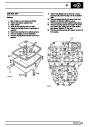
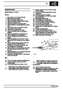
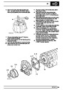
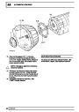
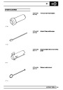
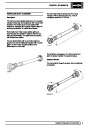
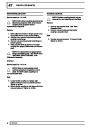
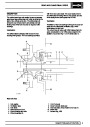
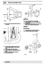
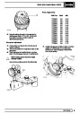
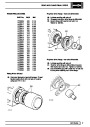
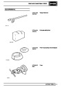
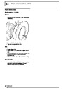
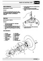
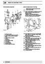
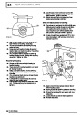
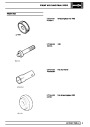
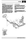
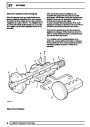
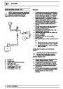
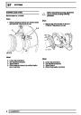
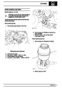
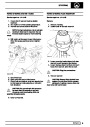
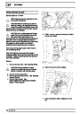
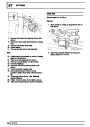
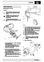
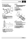
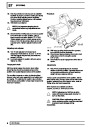
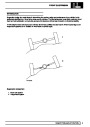
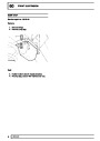
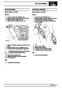
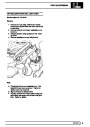
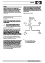
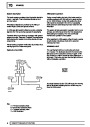
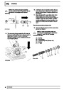
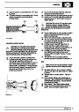
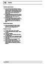
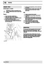
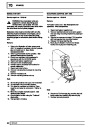
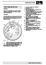
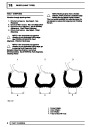
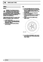
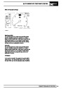
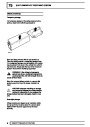
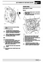
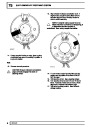
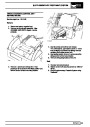
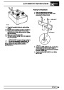
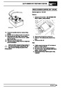
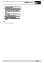
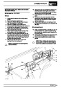
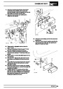
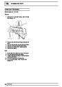
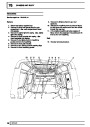
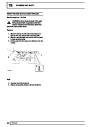
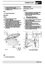
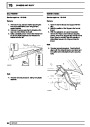
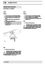
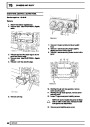
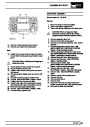
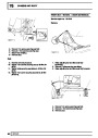
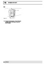
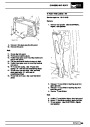
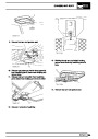
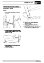
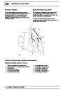
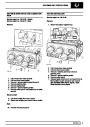
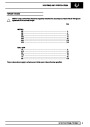
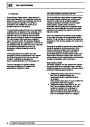
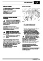
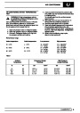
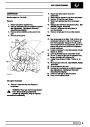
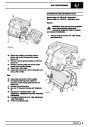
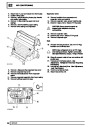
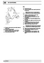
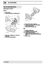
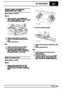
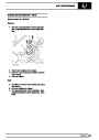
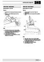
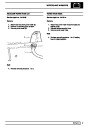
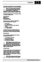
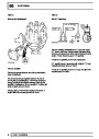
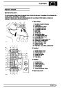
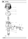
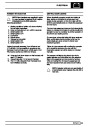
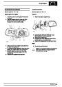
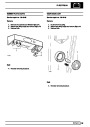
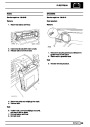
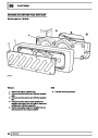
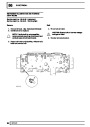
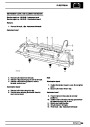
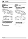
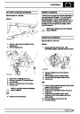
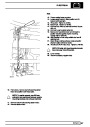
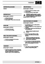
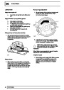
Drive pinion markings
NOTE: Markings on end face adjacent to
serial number are of no relevance to
servicing.
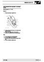
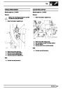
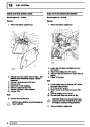
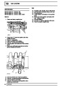
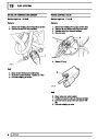
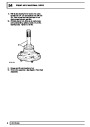
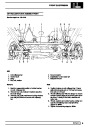
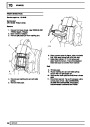
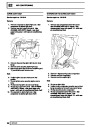
42.
Figures marked on end face opposite to serial
number show in thousandths of an inch,
deviation from nominal, required to set pinion.
Pinions marked plus (+) must be set below
nominal. Pinions marked minus (-) must be set
above nominal. Unmarked pinions must be set at
nominal.
4
OVERHAUL
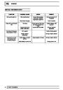
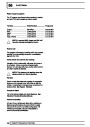
| Categories | Range Rover |
|---|---|
| Tags | Land Rover |
| Model Year | 1998 |
| Download File |
|
| Document Type | Workshop Manual |
| Language | English |
| Product Brand | Land Rover |
| Document File Type | |
| Publisher | landrover.com |
| Wikipedia's Page | http://en.wikipedia.org/wiki/Land_Rover |
| Copyright | Attribution Non-commercial |
(0 votes, average: 0 out of 5)