


82
AIR CONDITIONING
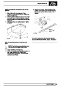
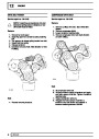
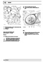
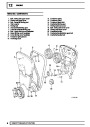
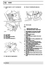
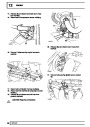
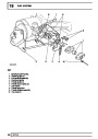
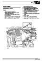
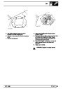
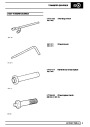
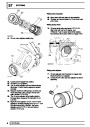
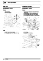
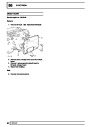
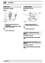
5.
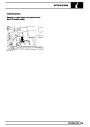
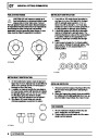
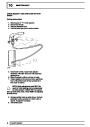
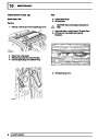
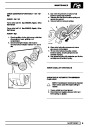
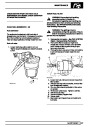
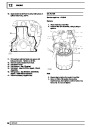
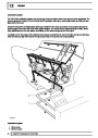
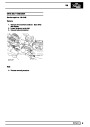
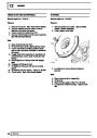
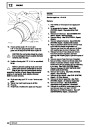
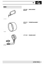
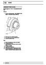
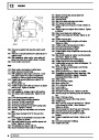
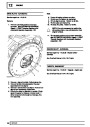
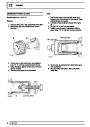
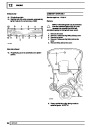
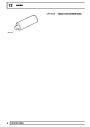
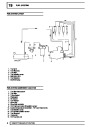
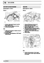
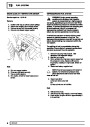
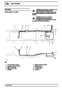
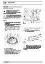
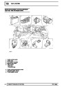
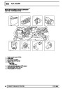
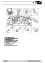
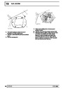
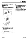
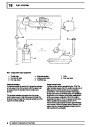
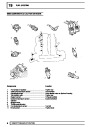
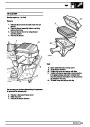
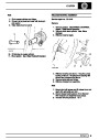
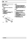
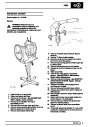
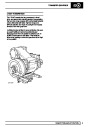
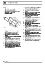
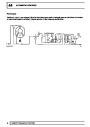
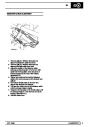
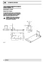
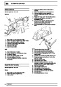
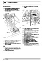
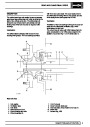
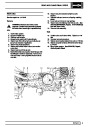
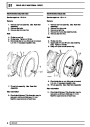
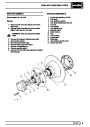
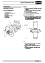
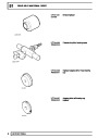
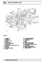
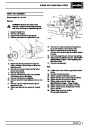
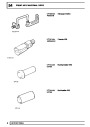
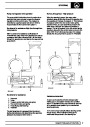
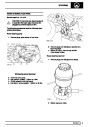
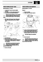
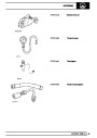
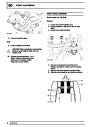
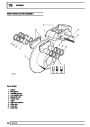
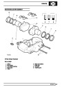
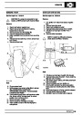
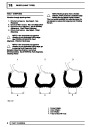
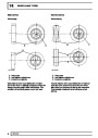
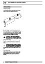
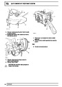
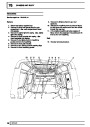
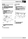
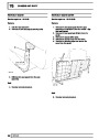
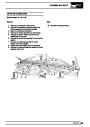
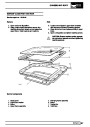
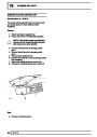
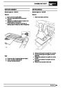
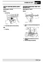
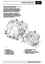
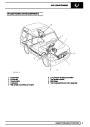
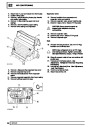
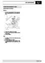
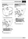
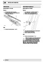
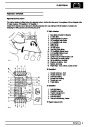
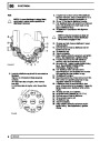
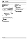
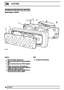
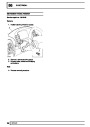
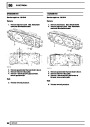
Evaporator
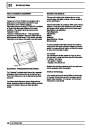
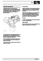
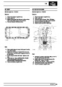
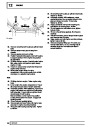
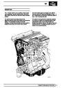
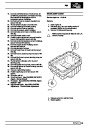
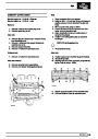
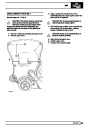
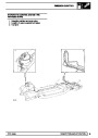
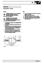
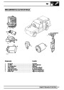
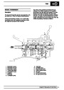
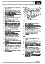
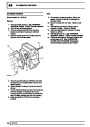
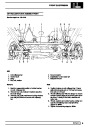
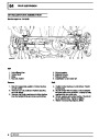
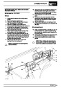
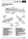
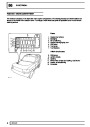
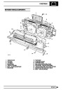
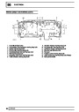
AIR CONDITIONING CONTROL SYSTEM
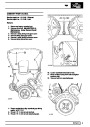
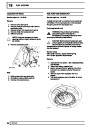
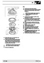
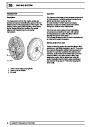
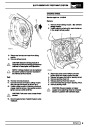
As this change of state occurs, a large amount of
latent heat is absorbed. The evaporator is therefore
cooled and as a result heat is extracted from the air
flowing across the evaporator. The air flow is
controlled by the ventilation fan which can be
operated at anyone of four speeds.
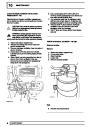
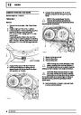
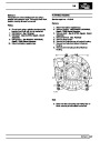
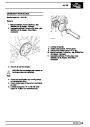
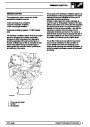
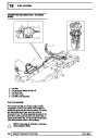
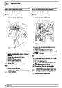
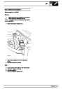
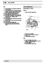
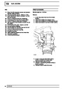
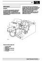
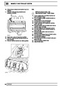
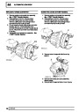
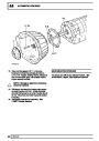
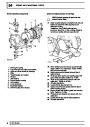
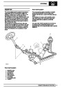
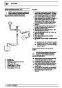
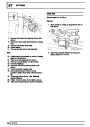
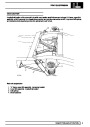
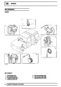
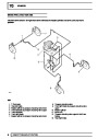
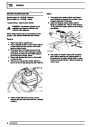
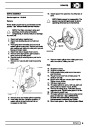
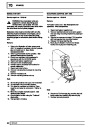
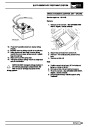
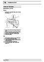
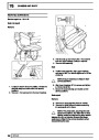
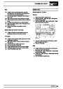
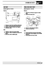
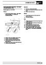
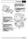
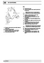
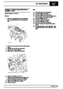
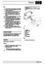
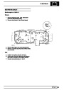
The air conditioning control system comprises relays,
thermostat, pressure switches, and a control panel.
Inputs from outside the air conditioning system
comprise temperature information from the engine
cooling system. Together these controls, in
conjunction with the cooling fans, compressor clutch,
blower and heater distribution and blend unit enable
minimal input to maintain the required environment
inside the vehicle.
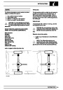
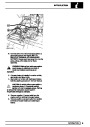
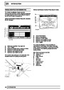
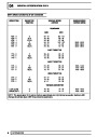
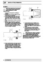
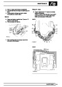
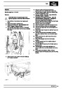
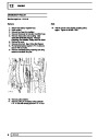
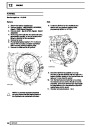
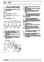
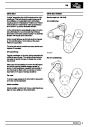
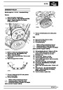
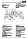
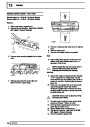
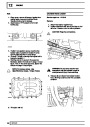
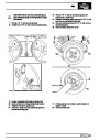
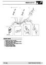
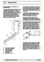
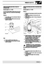
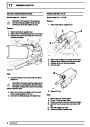
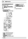
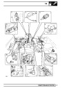
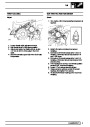
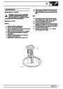
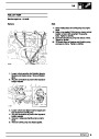
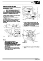
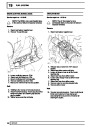
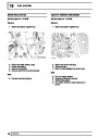
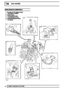
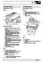
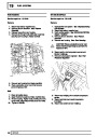
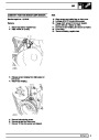
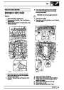
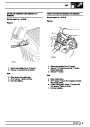
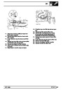
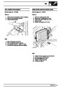
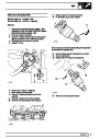
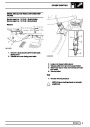
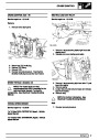
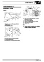
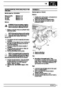
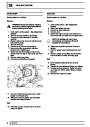
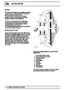
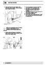
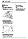
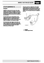
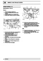
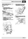
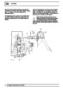
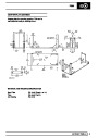
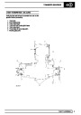
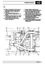
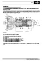
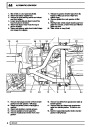
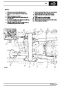
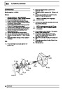
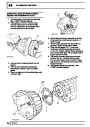
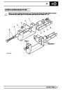
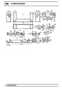
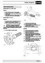
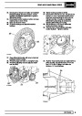
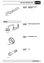
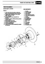
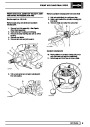
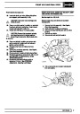
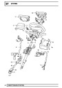
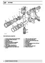
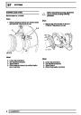
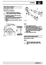
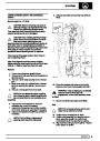
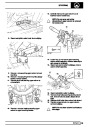
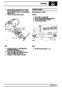
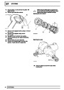
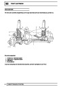
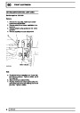
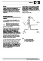
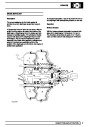
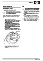
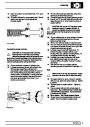
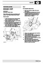
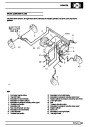
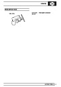
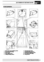
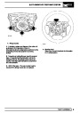
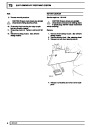
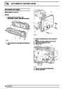
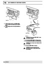
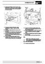
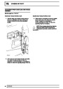
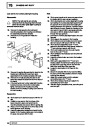
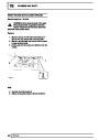
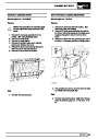
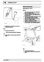
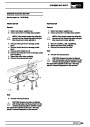
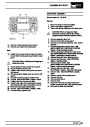
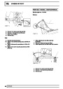
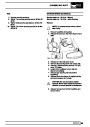
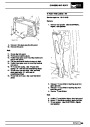
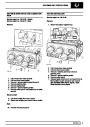
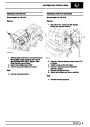
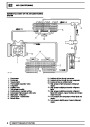
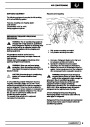
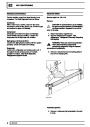
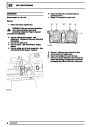
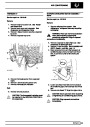
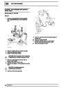
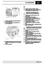
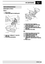
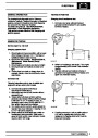
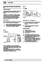
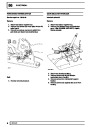
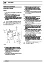
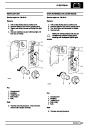
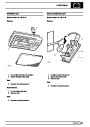
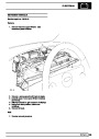
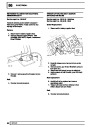
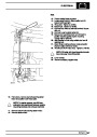
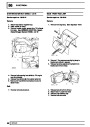
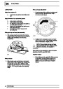
To prevent liquid passing through to the compressor,
a capillary tube (6), attached to the outlet pipe of the
evaporator (5) and connected to the thermostatic
expansion valve (4), controls the amount that the
valve opens and closes in relation to the temperature
of the low pressure high temperature refrigerant
vapour (F4) at the outlet. The atomised refrigerant
then passes through the evaporator (5). Fan blown air
(A2) passes through the matrix (A3) of the evaporator
and is cooled by absorption due to the low
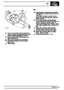
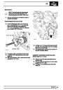
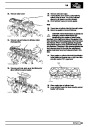
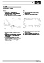
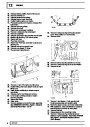
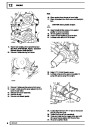
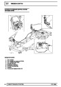
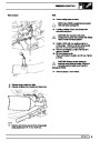
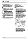
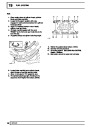
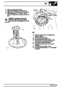
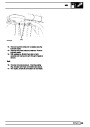
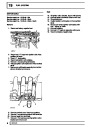
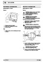
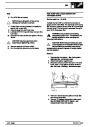
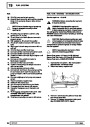
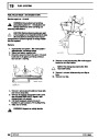
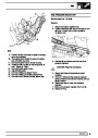
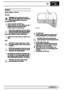
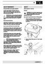
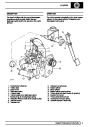
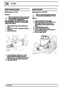
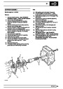
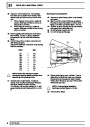
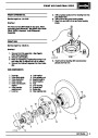
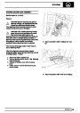
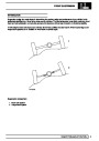
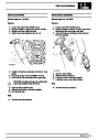
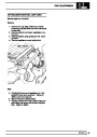
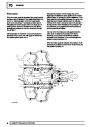
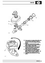
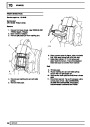
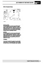
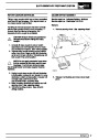
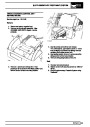
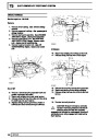
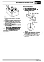
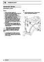
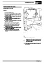
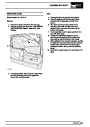
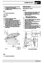
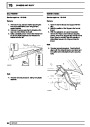
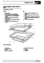
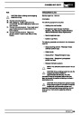
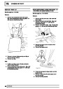
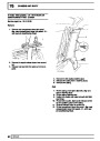
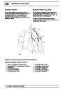
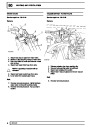
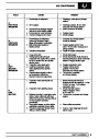
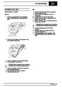
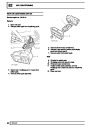
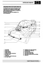
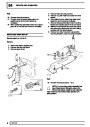
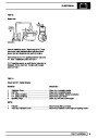
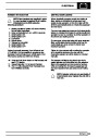
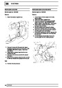
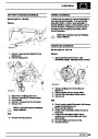
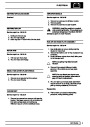
When air conditioning is not selected, air is supplied
by ram effect or blower to the areas selected by the
controls. The air mix flap on the blend unit controls the
temperature of the air being supplied. No cooled air is
available.
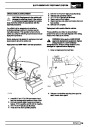
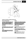
Selecting air conditioning provides the added facility of
cooled air available to be mixed as before. When
required a fully cold condition can be selected by
turning the temperature controls to cold, which
automatically closes the heated coolant access to the
heater matrix. Mixtures of cooled, fresh, and hot air
can be selected to give required interior environmental
conditions by selection at the control panel.
temperature refrigerant passing through the
evaporator.
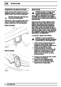
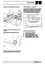
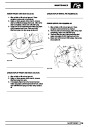
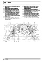
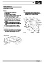
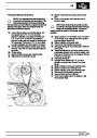
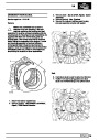
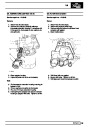
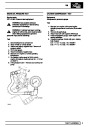
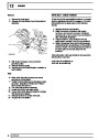
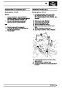
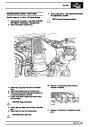
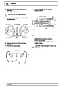
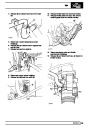
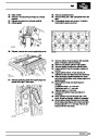
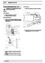
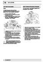
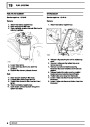
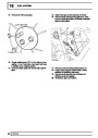
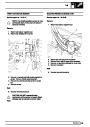
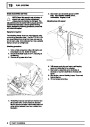
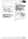
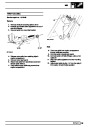
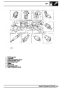
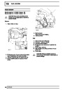
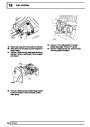
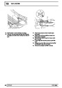
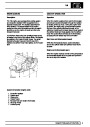
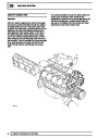
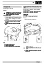
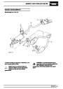
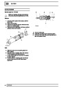
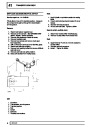
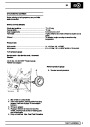
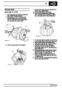
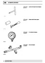
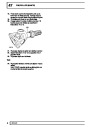
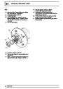
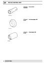
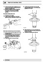
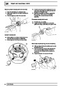
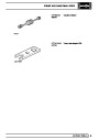
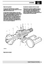
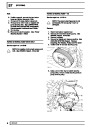
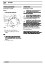
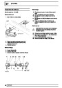
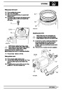
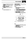
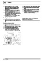
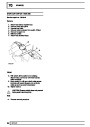
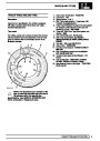
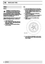
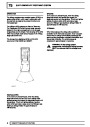
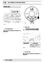
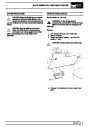
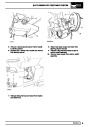
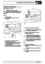
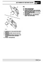
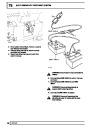
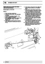
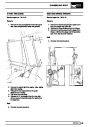
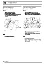
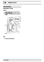
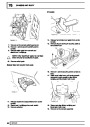
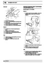
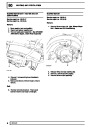
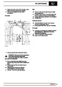
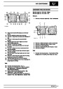
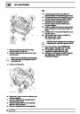
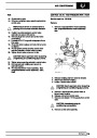
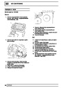
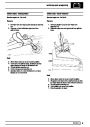
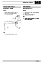
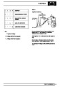
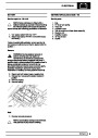
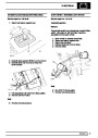
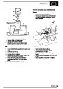
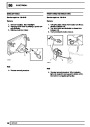
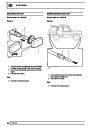
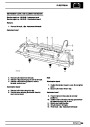
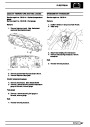
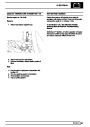
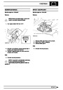
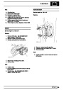
A thermostat is fitted in the airflow out of the
evaporator to sense the temperature of the exterior
fins. Should ice begin to form, due to a too cold
condition, it will signal to disengage the
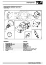
electro-mechanical clutch on the compressor (1).
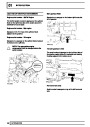
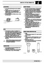
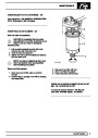
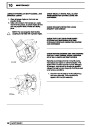
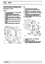
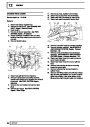
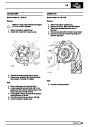
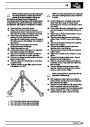
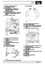
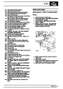
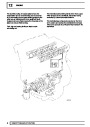
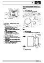
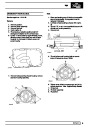
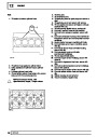
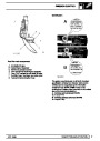
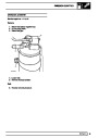
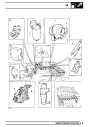
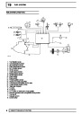
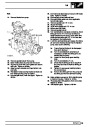
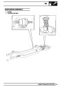
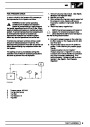
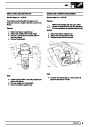
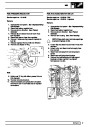
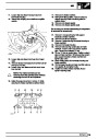
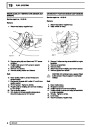
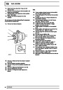
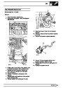
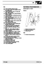
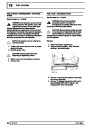
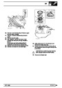
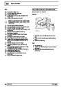
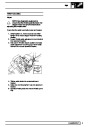
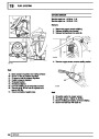
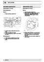
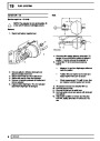
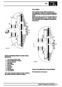
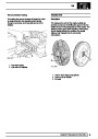
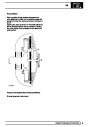
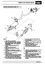
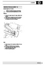
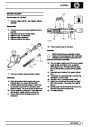
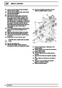
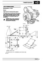
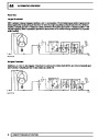
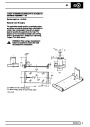
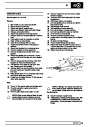
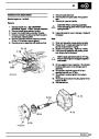
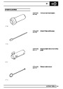
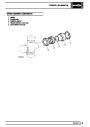
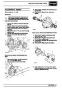
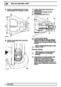
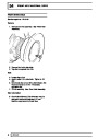
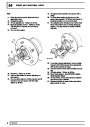
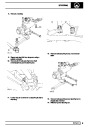
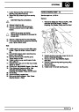
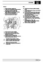
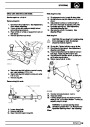
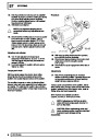
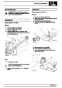
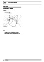
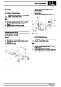
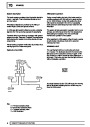
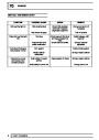
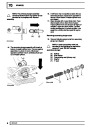
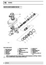
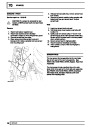
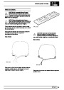
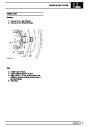
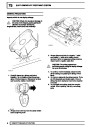
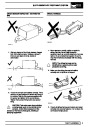
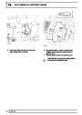
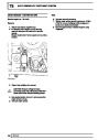
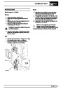
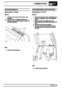
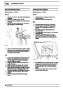
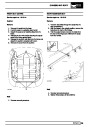
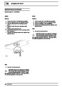
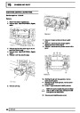
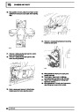
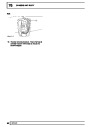
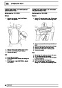
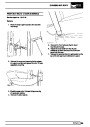
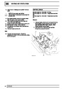
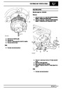
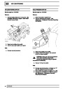
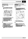
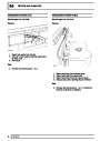
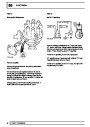
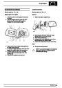
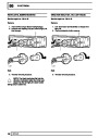
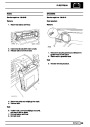
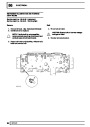
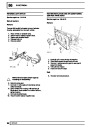
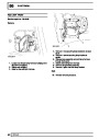
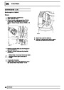
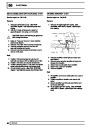
Dual pressure switch
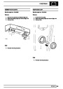
From the evaporator, low pressure slightly
superheated refrigerant (F5) passes to the
compressor to complete the cycle.
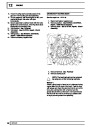
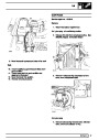
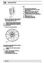
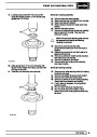
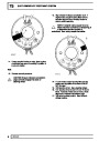
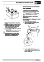
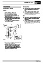
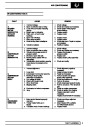
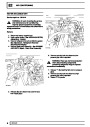
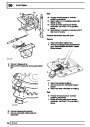
This switch, located in the high pressure line between
the receiver drier and the expansion valve, monitors
refrigerant pressure and by means of the relay module
controls the following system functions:
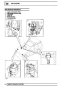
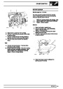
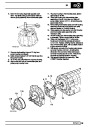
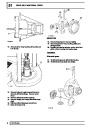
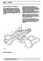
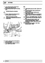
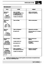
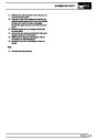
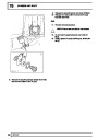
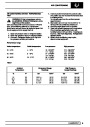
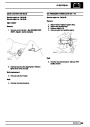
1.
Refrigerant pressure drops below 2.0 bar, 29
(due to possible leakage), the
lbf/in
2
compressor’s electro-mechanical clutch is
dis-engaged.
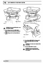
2
When pressure rises above 2.0 bar, 29 lbf/in the
compressor’s clutch is re-engaged.
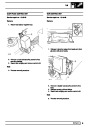
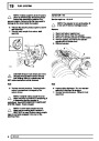
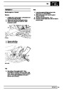
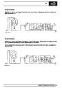
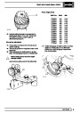
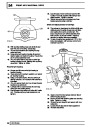
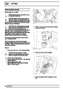
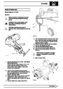
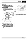
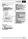
2.
Refrigerant pressure rises above 32 bar, 455
(due to possible blockage), even with
lbf/in
2
cooling fan operation, the compressor’s
electro-mechanical clutch is dis-engaged.
When the pressure drops below 26 bar, 375
lbf/in the compressor clutch is re-engaged.
2
4
DESCRIPTION AND OPERATION
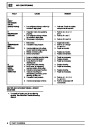
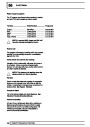
| Categories | Range Rover |
|---|---|
| Tags | Land Rover |
| Model Year | 1998 |
| Download File |
|
| Document Type | Workshop Manual |
| Language | English |
| Product Brand | Land Rover |
| Document File Type | |
| Publisher | landrover.com |
| Wikipedia's Page | http://en.wikipedia.org/wiki/Land_Rover |
| Copyright | Attribution Non-commercial |
(0 votes, average: 0 out of 5)