


82
AIR CONDITIONING
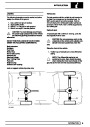
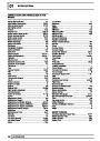
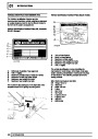
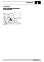
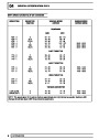
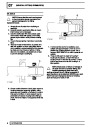
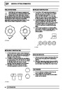
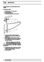
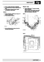
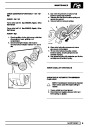
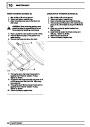
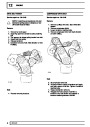
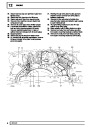
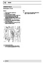
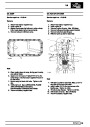
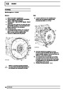
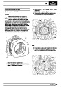
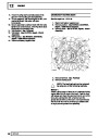
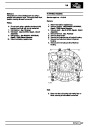
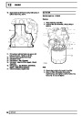
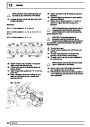
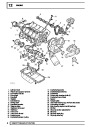
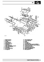
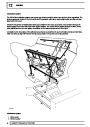
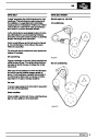
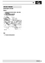
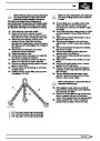
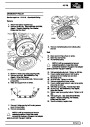
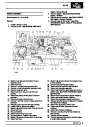
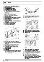
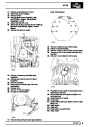
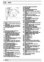
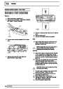
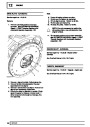
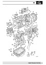
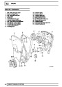
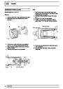
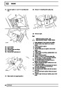
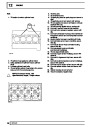
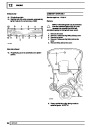
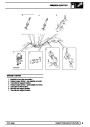
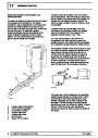
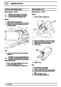
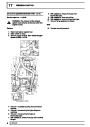
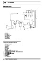
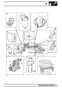
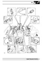
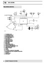
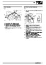
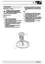
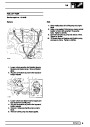
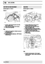
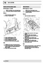
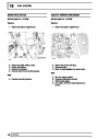
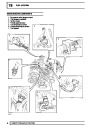
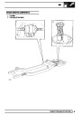
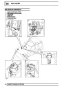
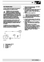
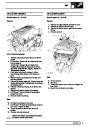
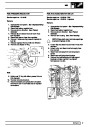
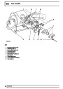
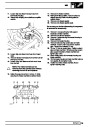
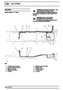
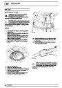
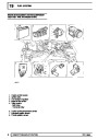
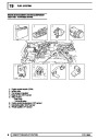
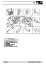
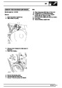
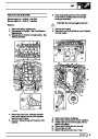
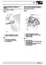
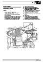
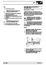
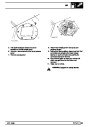
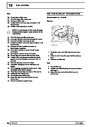
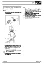
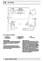
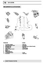
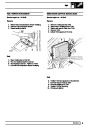
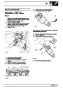
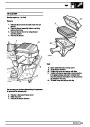
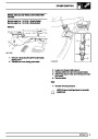
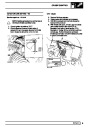
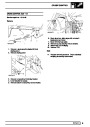
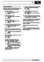
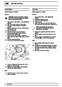
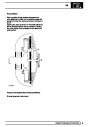
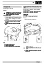
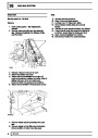
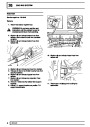
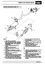
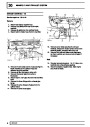
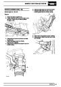
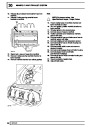
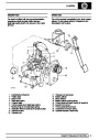
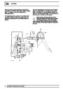
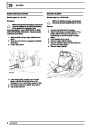
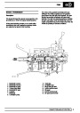
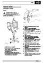
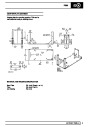
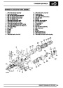
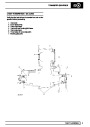
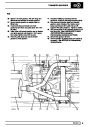
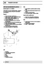
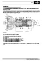
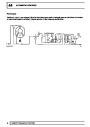
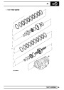
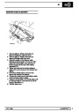
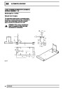
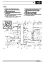
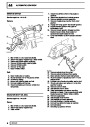
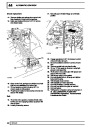
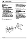
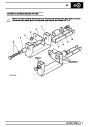
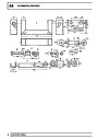
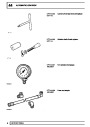
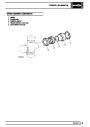
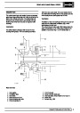
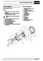
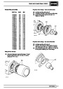
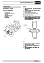
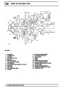
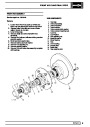
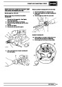
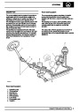
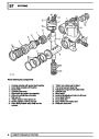
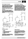
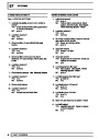
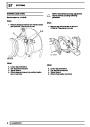
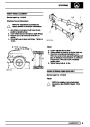
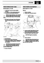
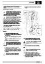
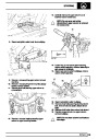
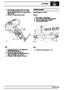
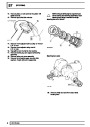
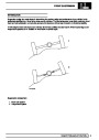
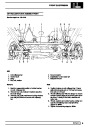
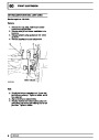
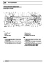
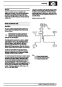
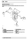
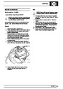
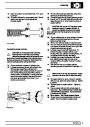
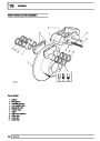
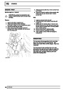
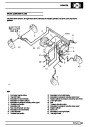
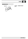
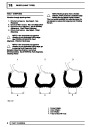
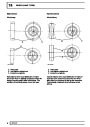
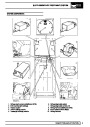
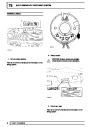
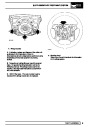
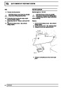
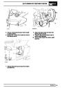
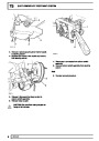
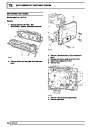
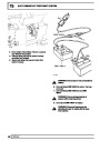
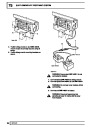
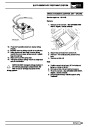
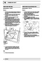
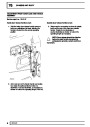
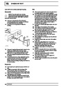
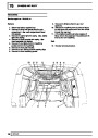
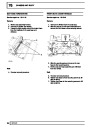
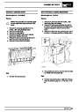
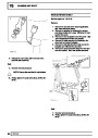
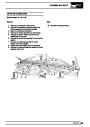
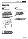
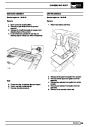
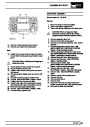
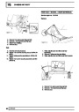
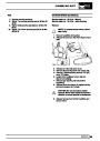
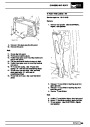
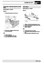
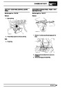
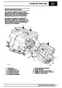
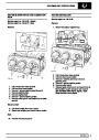
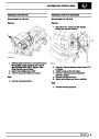
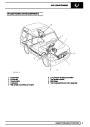
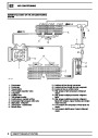
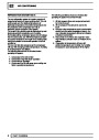
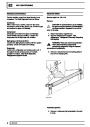
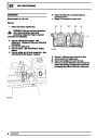
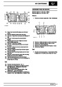
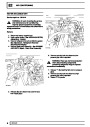
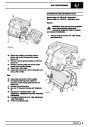
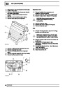
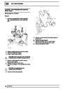
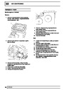
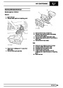
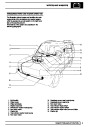
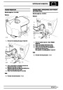
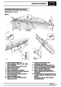
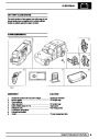
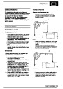
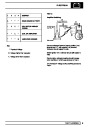
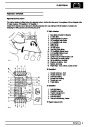
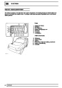
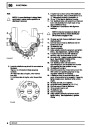
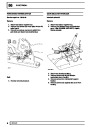
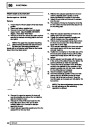
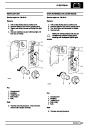
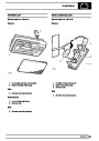
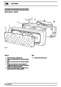
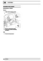
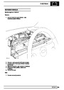
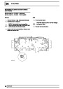
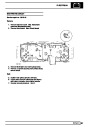
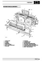
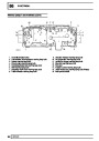
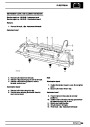
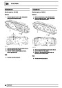
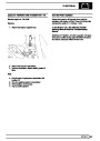
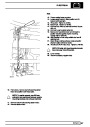
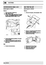
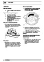
SCHEMATIC LAYOUT OF THE AIR CONDITIONING
SYSTEM
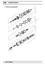
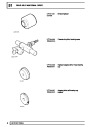
1.
2.
3.
4.
5.
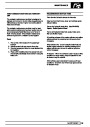
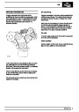
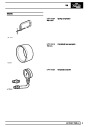
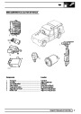
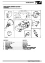
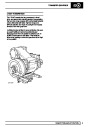
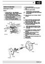
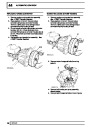
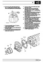
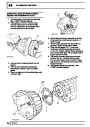
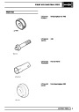
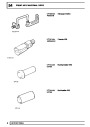
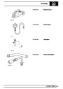
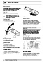
Compressor
Condenser
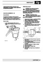
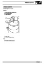
Receiver/drier
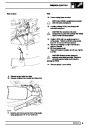
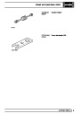
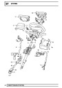
Thermostatic expansion valve
Evaporator
A1 Ambient air flow through condenser
A2 Ambient air flow through fan and evaporator
A3 Cooled air flow to vehicle interior
F1 High pressure high temperature refrigerant
vapour
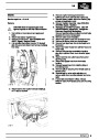
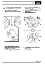
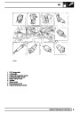
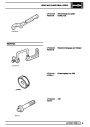
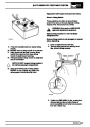
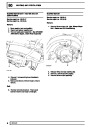
6.
7.
8.
9.
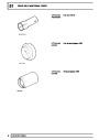
10.
11.
12.
Capillary tube
F2 High pressure slightly subcooled refrigerant
liquid
F3 High pressure slightly subcooled refrigerant
liquid with moisture, vapour bubbles and foreign
matter removed
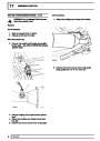
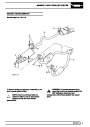
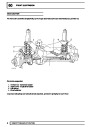
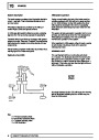
Dual pressure switch
Cooling fans to maintain air flow
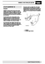
Compressor high pressure relief valve
Sight glass - refrigerant
Drying agent - receiver/drier
Blower motor
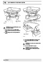
F4 Low pressure low temperature mixed liquid and
vapour
F5 Low pressure slightly super heated refrigerant
vapour
2
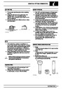
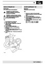
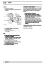
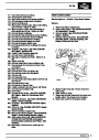
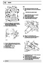
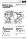
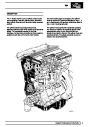
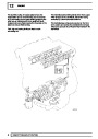
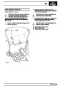
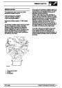
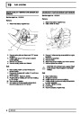
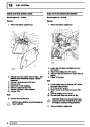
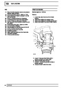
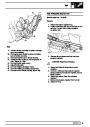
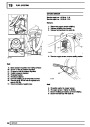
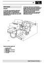
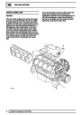
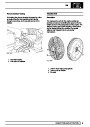
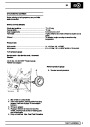
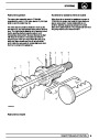
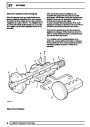
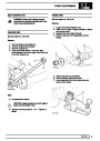
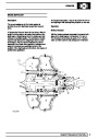
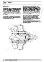
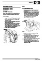
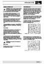
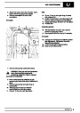
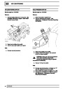
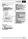
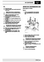
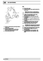
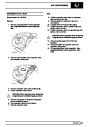
DESCRIPTION AND OPERATION
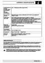
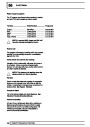
| Categories | Range Rover |
|---|---|
| Tags | Land Rover |
| Model Year | 1998 |
| Download File |
|
| Document Type | Workshop Manual |
| Language | English |
| Product Brand | Land Rover |
| Document File Type | |
| Publisher | landrover.com |
| Wikipedia's Page | http://en.wikipedia.org/wiki/Land_Rover |
| Copyright | Attribution Non-commercial |
(0 votes, average: 0 out of 5)