


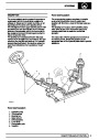


SFI
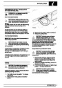
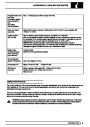
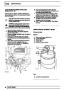
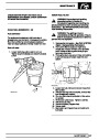
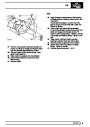
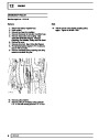
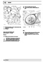
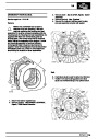
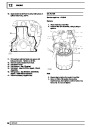
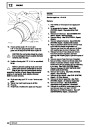
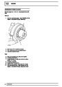
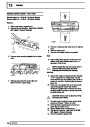
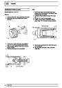
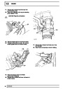
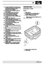
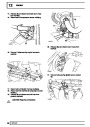
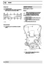
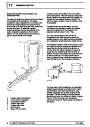
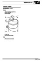
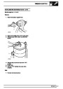
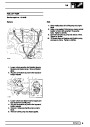
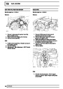
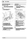
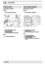
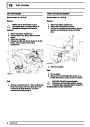
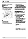
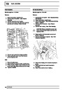
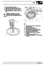
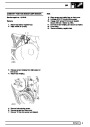
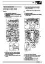
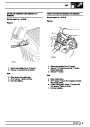
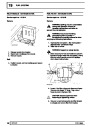
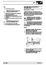
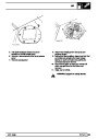
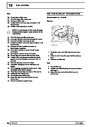
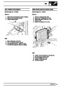
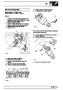
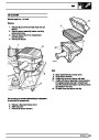
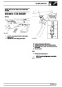
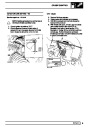
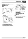
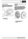
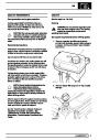
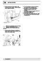
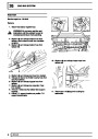
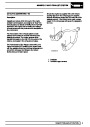
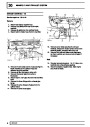
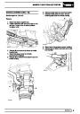
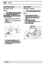
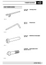
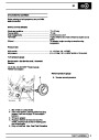
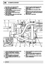
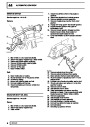
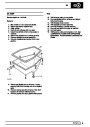
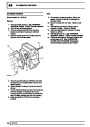
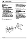
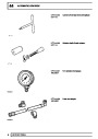
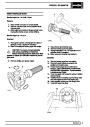
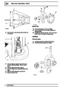
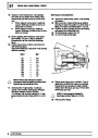
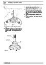
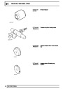
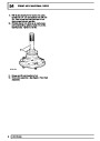
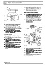
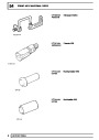
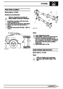
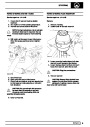
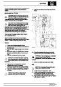
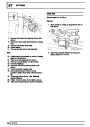
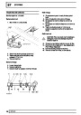
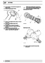
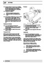
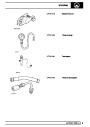
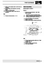
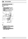
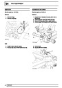
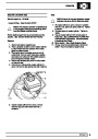
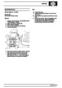
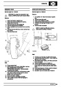
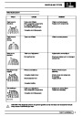
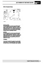
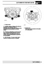
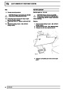
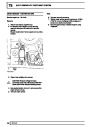
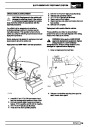
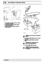
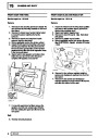
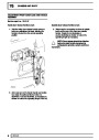
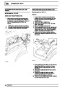
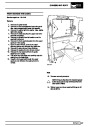
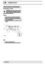
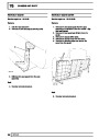
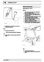
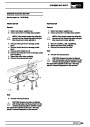
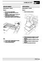
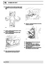
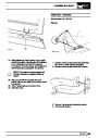
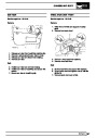
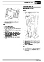
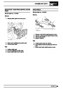
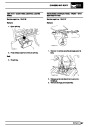
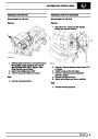
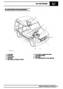
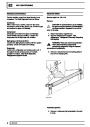
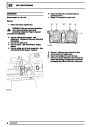
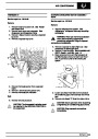
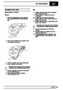
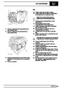
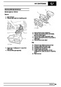
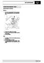
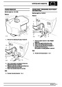
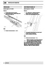
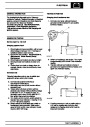
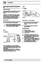
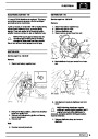
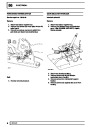
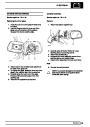
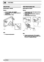
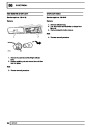
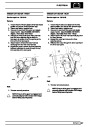
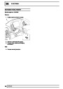
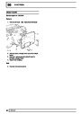
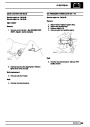
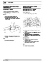
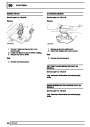
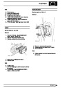
Engine fuel temperature sensor (EFT Sensor)
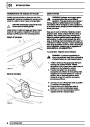
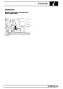
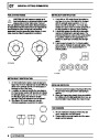
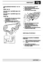
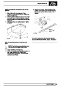
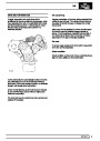
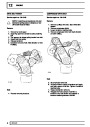
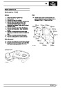
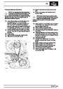
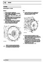
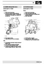
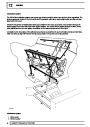
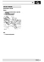
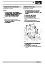
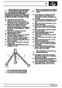
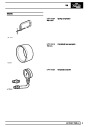
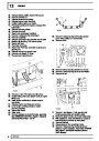
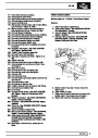
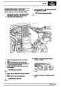
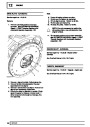
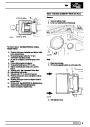
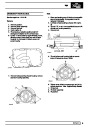
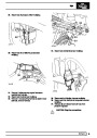
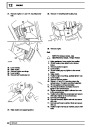
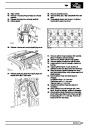
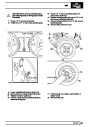
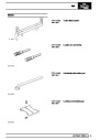
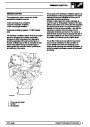
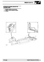
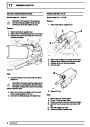
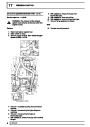
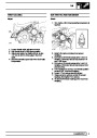
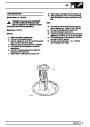
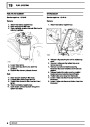
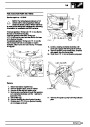
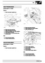
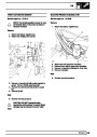
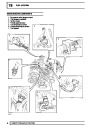
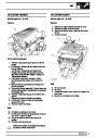
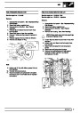
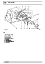
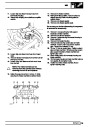
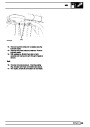
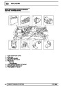
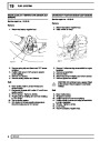
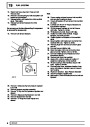
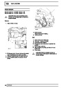
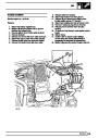
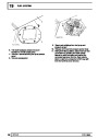
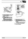
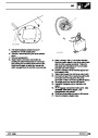
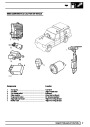
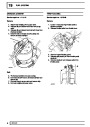
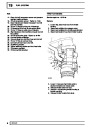
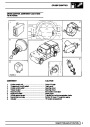
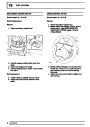
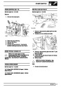
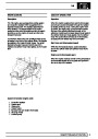
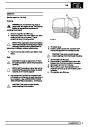
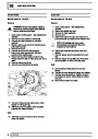
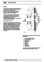
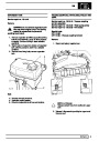
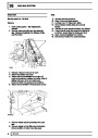
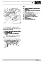
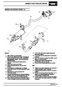
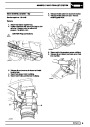
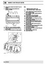
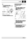
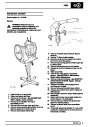
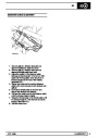
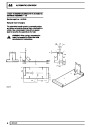
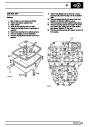
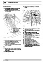
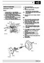
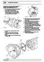
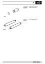
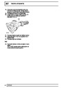
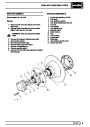
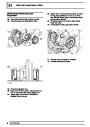
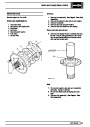
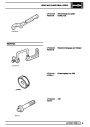
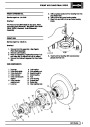
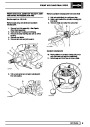
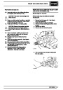
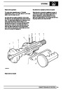
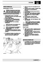
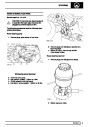
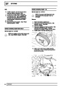
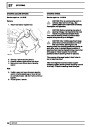
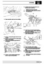
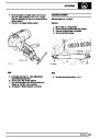
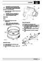
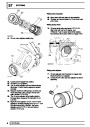
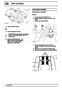
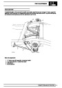
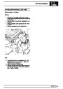
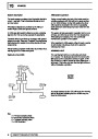
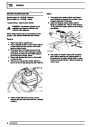
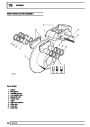
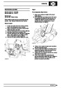
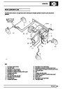
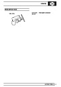
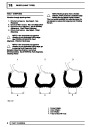
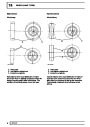
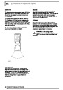
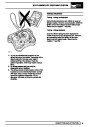
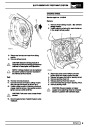
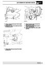
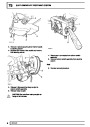
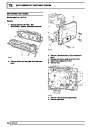
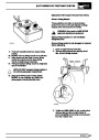
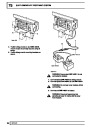
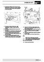
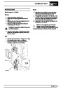
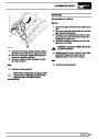
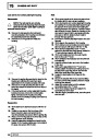
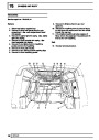
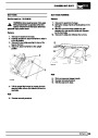
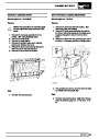
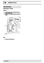
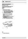
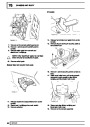
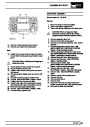
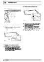
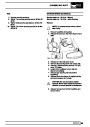
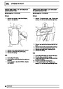
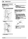
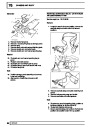
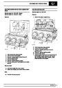
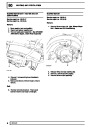
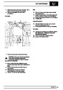
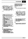
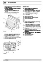
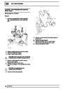
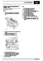
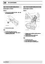
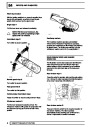
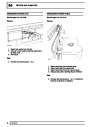
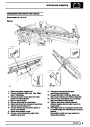
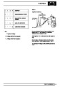
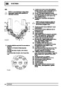
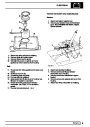
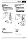
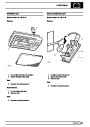
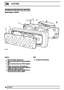
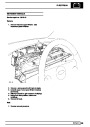
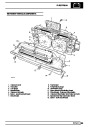
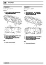
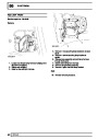
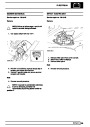
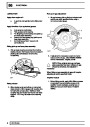
Ignition coils
This is another resistive sensor. Located on the fuel
rail it measures temperature of the rail rather than the
fuel. The resistance varies with changes in
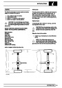
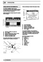
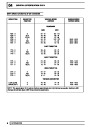
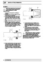
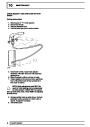
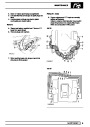
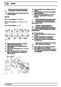
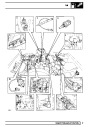
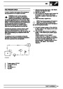
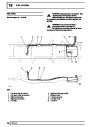
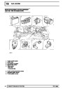
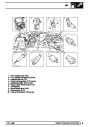
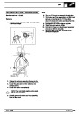
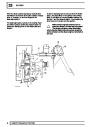
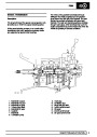
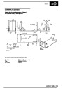
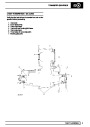
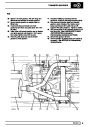
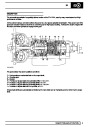
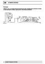
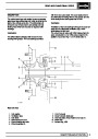
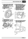
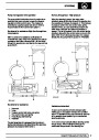
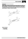
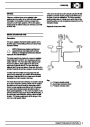
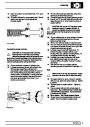
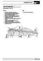
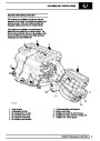
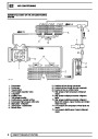
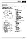
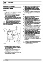
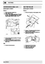
The electronic ignition system uses four double ended
coils. They are mounted on a bracket fitted to the rear
of the engine. The circuit to each coil is completed by
switching within the ECM, allowing each coil to charge
up and fire. Sparks are produced in two cylinders
simultaneously, one on compression stroke, the other
on exhaust stroke. Note that coil 1 feeds cylinders 1
and 6, coil 2 feeds cylinders 5 and 8, coil 3 feeds
cylinders 4 and 7, and coil 4 feeds cylinders 2 and 3.
Due to the ease of combustion in the cylinder on the
compression stroke, more energy is dissipated in that
cylinder. Coil failure will result in a lack of sparks and
misfire in the affected cylinders. The fault is indicated
by illumination of the malfunction indicator light (MIL)
on North American specification vehicles.
temperature. The signal is used to increase the
injection pulse time when undergoing hot restarts.
When the fuel is hot, vapourisation occurs in the rail
and bubbles can occur in the injectors. Increasing the
pulse time flushes the bubbles away, and cools the
fuel rail with fuel from the tank. The fault may not be
evident to the driver, there may be a hot restart
problem. The fault is indicated by illumination of the
malfunction indicator light (MIL) on North American
specification vehicles.
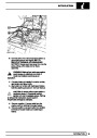
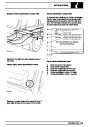
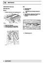
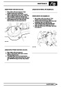
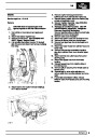
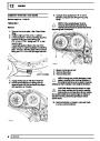
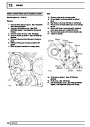
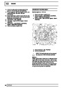
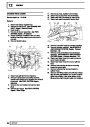
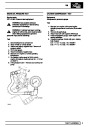
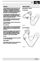
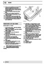
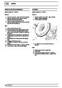
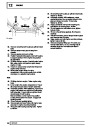
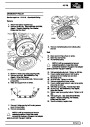
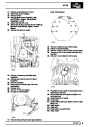
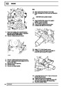
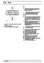
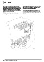
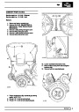
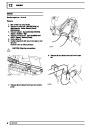
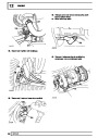
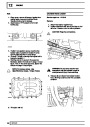
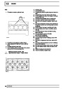
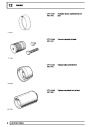
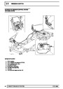
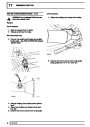
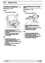
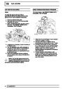
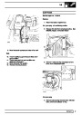
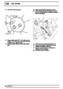
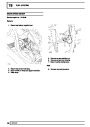
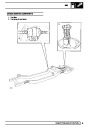
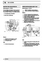
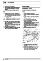
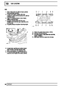
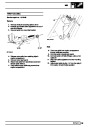
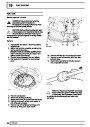
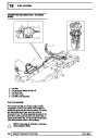
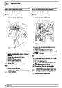
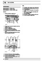
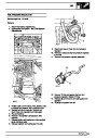
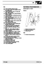
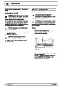
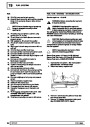
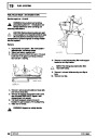
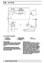
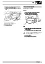
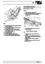
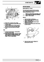
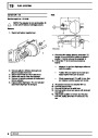
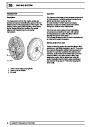
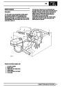
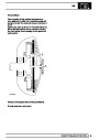
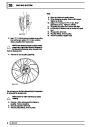
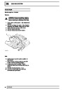
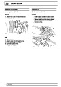
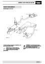
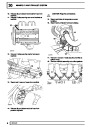
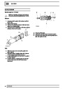
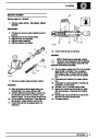
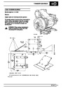
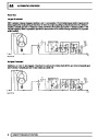
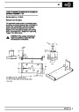
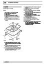
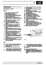
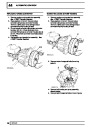
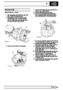
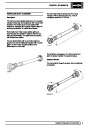
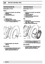
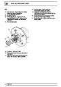
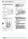
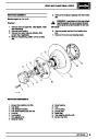
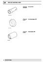
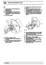
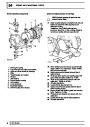
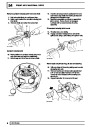
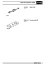
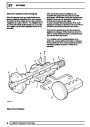
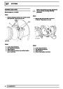
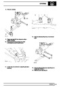
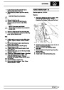
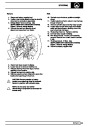
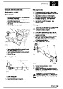
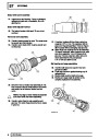
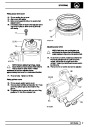
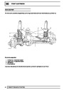
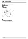
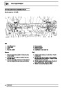
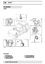
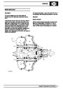
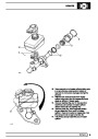
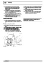
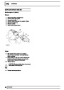
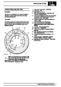
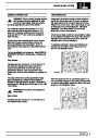
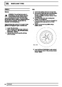
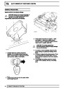
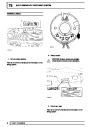
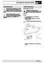
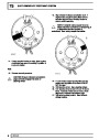
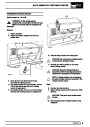
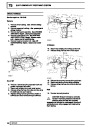
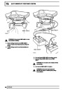
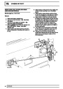
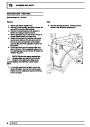
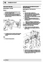
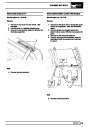
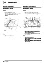
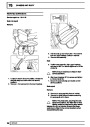
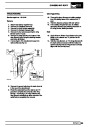
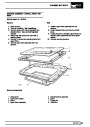
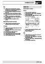
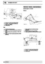
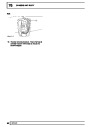
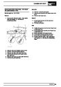
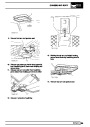
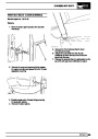
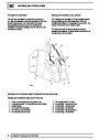
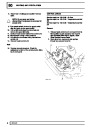
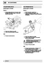
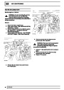
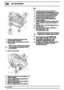
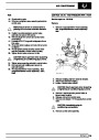
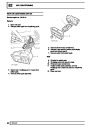
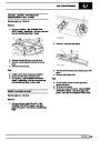
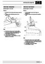
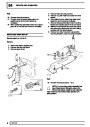
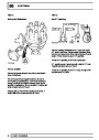
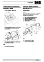
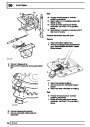
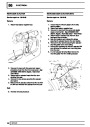
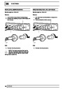
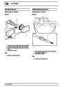
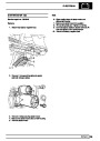
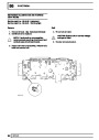
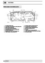
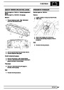
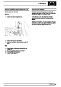
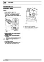
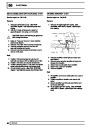
Knock sensors
The knock sensor produces an output voltage in
proportion to mechanical vibration caused by the
engine. A sensor is located in each cylinder bank
between 2/4 and 3/5 cylinders. The ECM calculates if
the engine is knocking due to camshaft and
crankshaft sensor signals regarding the position of the
engine in the cycle. The ECM can also work out
exactly which cylinder is knocking and retards the
ignition on that particular cylinder until the knock
disappears. It then advances the ignition to find the
optimum ignition timing for that cylinder. The ECM can
adjust the timing of each cylinder for knock
simultaneously. It is possible that all eight cylinders
could have different advance angles at the same time.
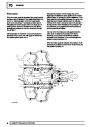
If the camshaft sensor fails, the knock sensor will
continue to work, but as the engine may be running
one revolution out of sychronisation the ECM may
retard the wrong cylinder of the pair e.g. 1 instead of
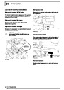
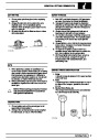
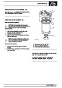
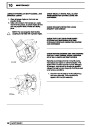
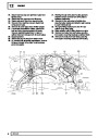
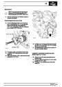
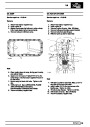
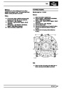
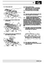
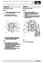
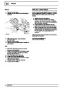
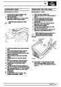
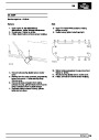
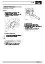
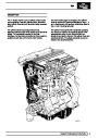
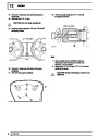
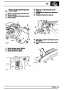
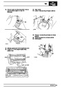
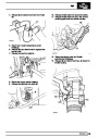
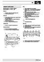
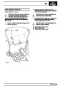
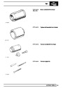
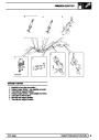
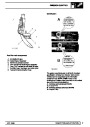
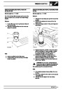
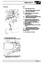
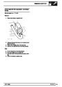
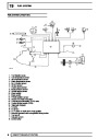
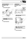
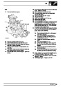
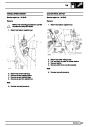
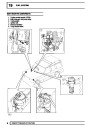
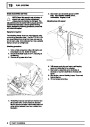
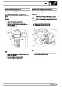
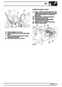
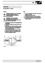
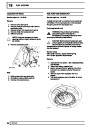
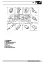
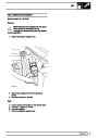
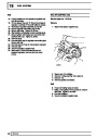
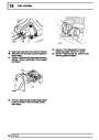
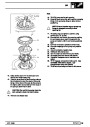
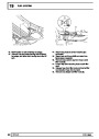
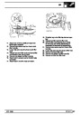
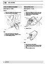
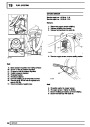
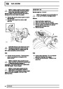
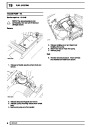
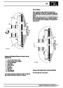
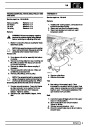
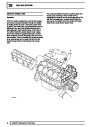
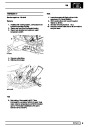
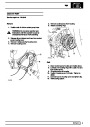
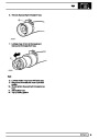
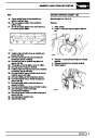
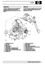
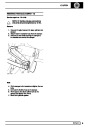
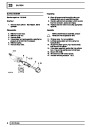
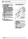
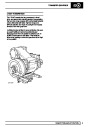
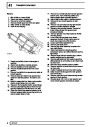
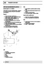
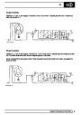
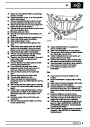
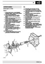
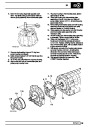
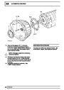
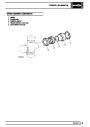
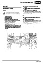
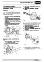
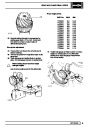
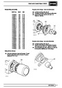
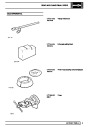
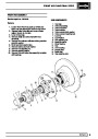
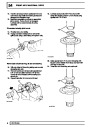
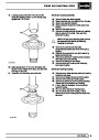
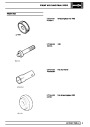
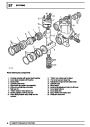
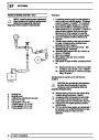
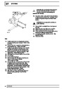
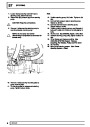
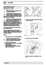
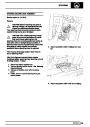
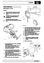
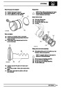
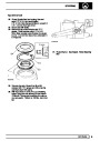
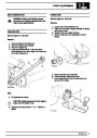
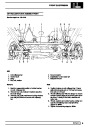
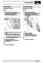
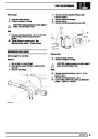
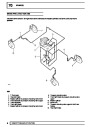
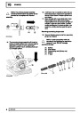
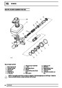
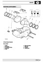
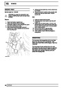
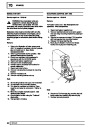
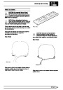
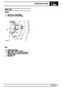
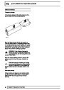
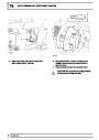
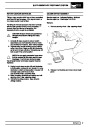
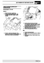
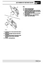
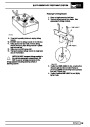
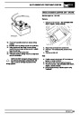
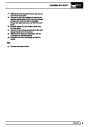
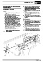
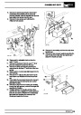
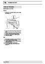
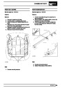
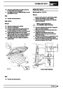
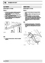
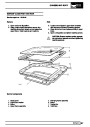
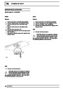
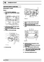
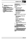
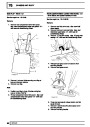
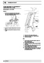
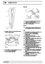
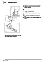
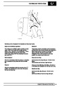
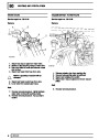
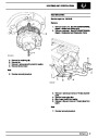
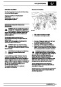
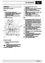
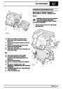
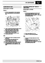
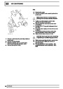
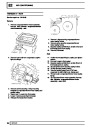
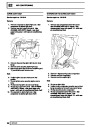
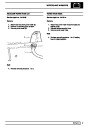
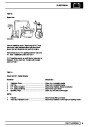
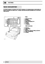
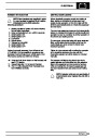
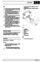
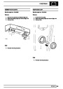
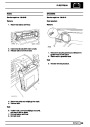
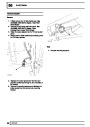
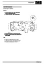
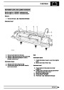
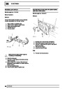
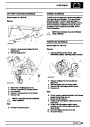
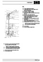
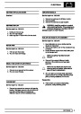
Injectors
A multiport fuel injection system (MFI) is used, one
injector per cylinder. Each injector consists of a small
solenoid which is activated by the ECM to allow a
metered amount of fuel to pass into the combustion
chamber. Due to the pressure in the fuel rail and the
shape of the injector orifice, the fuel squirts into the
cylinder in a fine spray to aid combustion. In the
unlikely event of injector failure a misfire will occur as
there will be no fuel to the affected cylinder. The fault
is indicated by illumination of the malfunction indicator
light (MIL) on North American specification vehicles.
6.
If the knock sensor fails engine knock will not be
detected and corrected. The fault is indicated by
illumination of the malfunction indicator light (MIL) on
North American specification vehicles.
REV: 09/95
DESCRIPTION AND OPERATION
5
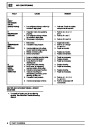
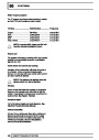
| Categories | Range Rover |
|---|---|
| Tags | Land Rover |
| Model Year | 1998 |
| Download File |
|
| Document Type | Workshop Manual |
| Language | English |
| Product Brand | Land Rover |
| Document File Type | |
| Publisher | landrover.com |
| Wikipedia's Page | http://en.wikipedia.org/wiki/Land_Rover |
| Copyright | Attribution Non-commercial |
(0 votes, average: 0 out of 5)