


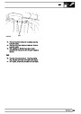


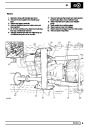


SFI
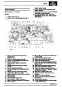
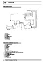
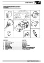
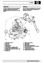
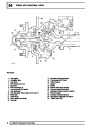
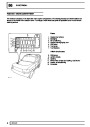
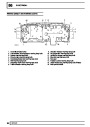
ENGINE MANAGEMENT SYSTEM
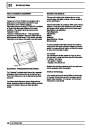
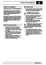
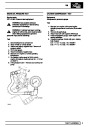
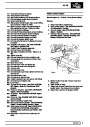
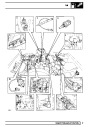
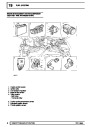
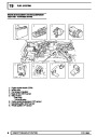
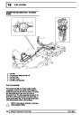
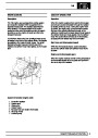
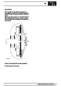
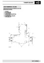
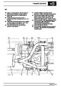
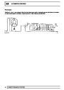
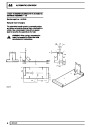
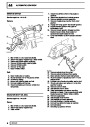
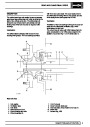
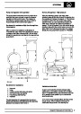
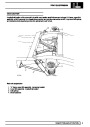
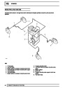
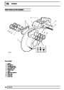
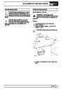
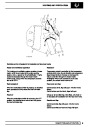
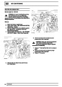
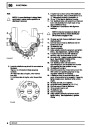
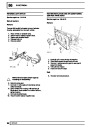
Description
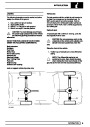
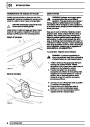
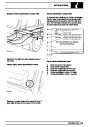
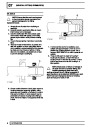
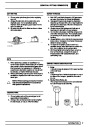
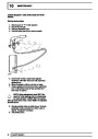
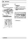
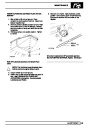
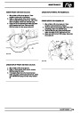
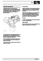
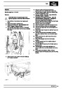
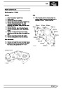
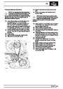
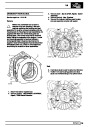
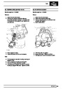
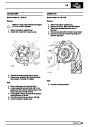
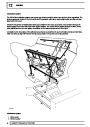
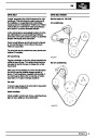
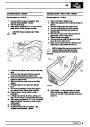
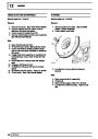
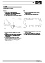
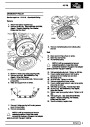
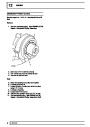
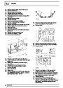
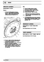
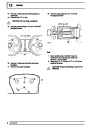
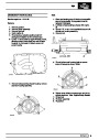
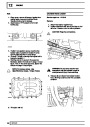
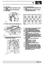
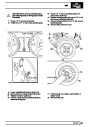
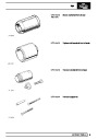
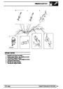
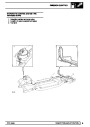
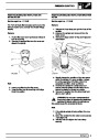
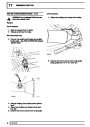
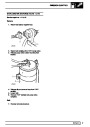
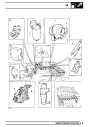
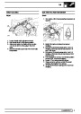
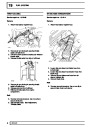
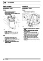
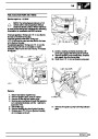
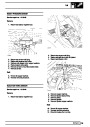
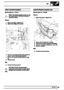
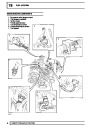
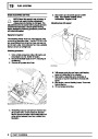
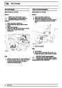
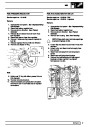
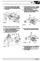
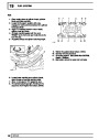
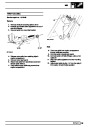
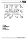
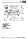
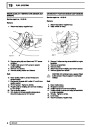
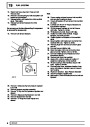
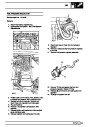
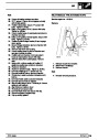
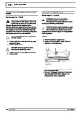
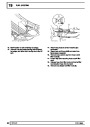
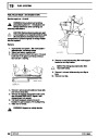
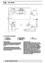
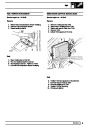
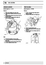
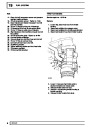
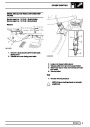
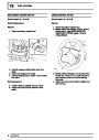
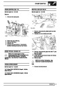
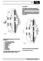
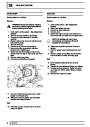
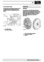
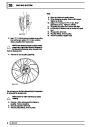
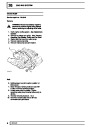
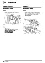
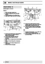
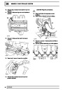
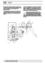
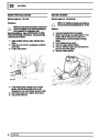
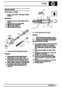
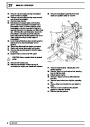
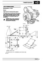
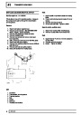
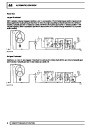
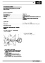
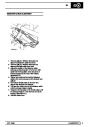
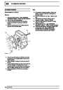
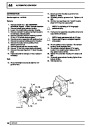
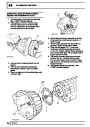
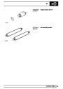
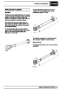
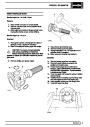
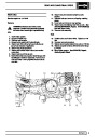
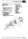
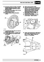
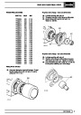
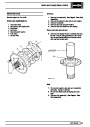
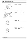
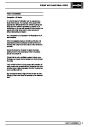
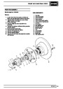
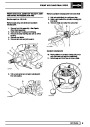
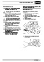
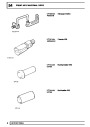
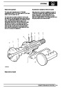
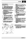
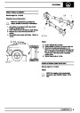
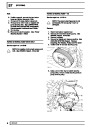
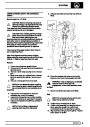
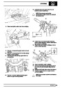
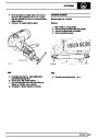
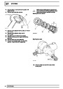
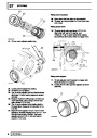
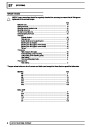
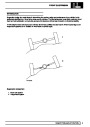
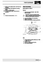
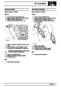
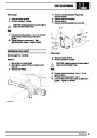
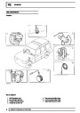
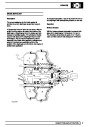
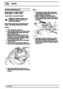
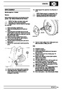
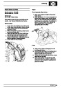
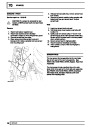
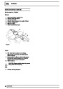
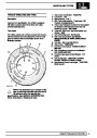
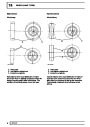
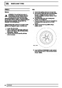
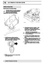
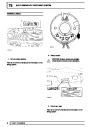
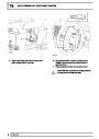
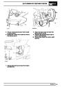
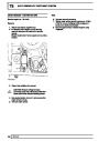
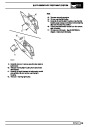
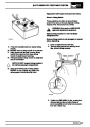
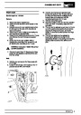
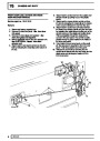
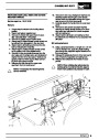
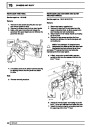
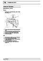
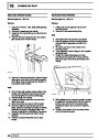
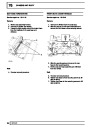
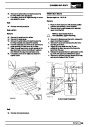
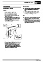
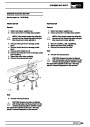
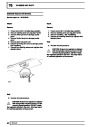
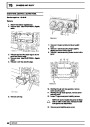
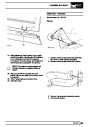
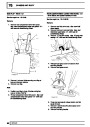
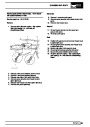
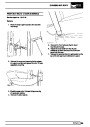
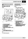
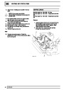
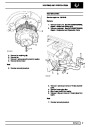
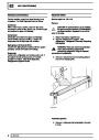
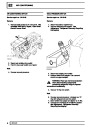
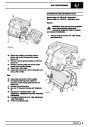
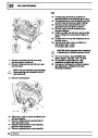
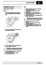
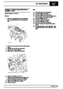
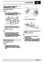
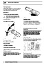
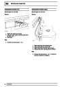
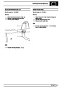
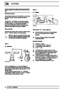
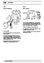
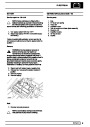
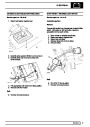
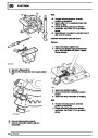
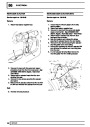
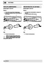
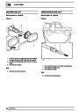
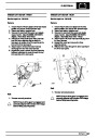
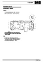
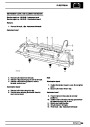
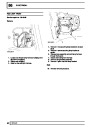
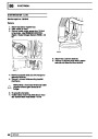
Crankshaft position sensor (CKP Sensor)
The crankshaft position sensor is the most important
sensor on the engine. It is located in the left hand side
of the flywheel housing and uses a different thickness
of spacer for manual and automatic gearboxes. The
signal it produces informs the ECM:
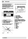
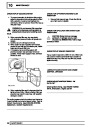
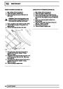
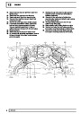
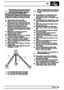
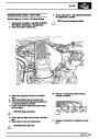
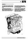
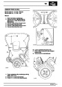
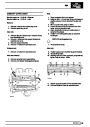
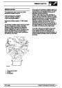
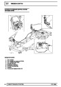
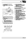
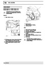
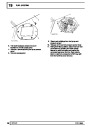
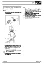
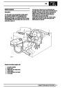
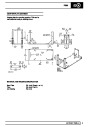
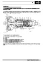
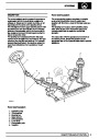
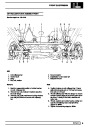
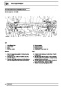
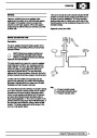
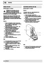
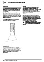
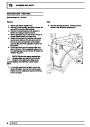
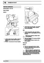
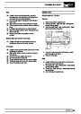
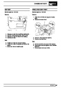
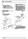
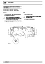
The engine management system (EMS) maintains
optimum engine performance over the entire
operating range. The correct amount of fuel is
metered into each cylinder inlet tract and the ignition
timing is adjusted at each spark plug.
- the engine is turning
- how fast the engine is turning
-
which stage the engine is at in the cycle.
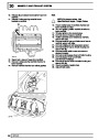
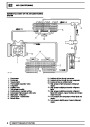
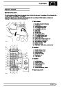
The system is controlled by the ENGINE CONTROL
MODULE (ECM) which receives data from sensors
located on and around the engine. From this
information it provides the correct fuel requirements
and ignition timing at all engine loads and speeds.
As there is no default strategy, failure of the
crankshaft sensor will result in the engine failing to
start. The fault is indicated by illumination of the
malfunction indicator light (MIL) on North American
specification vehicles.
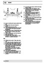
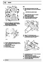
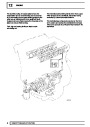
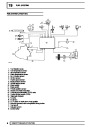
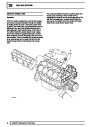
The fuel injection system uses a hot wire Mass Air
Flow Sensor to calculate the amount of air flowing into
the engine.
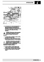
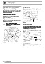
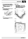
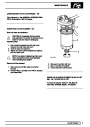
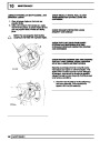
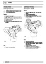
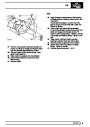
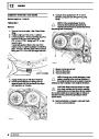
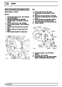
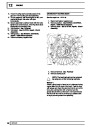
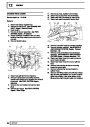
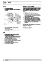
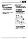
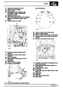
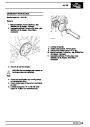
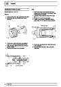
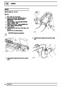
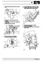
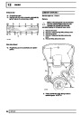
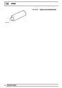
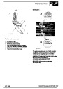
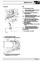
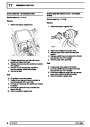
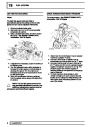
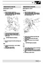
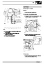
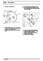
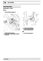
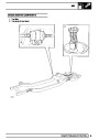
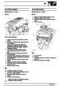
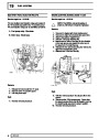
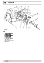
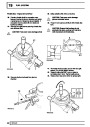
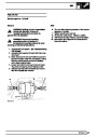
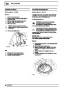
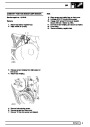
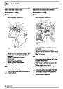
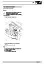
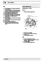
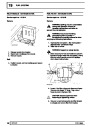
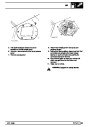
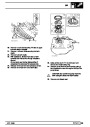
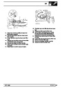
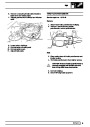
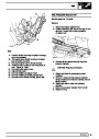
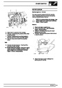
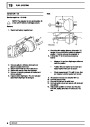
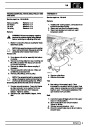
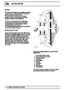
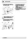
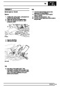
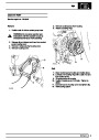
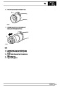
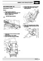
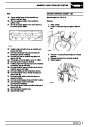
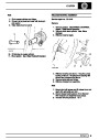
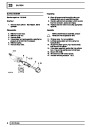
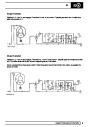
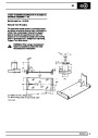
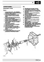
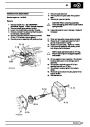
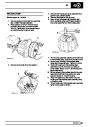
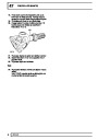
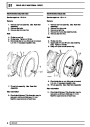
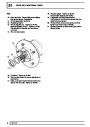
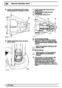
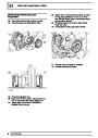
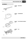
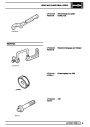
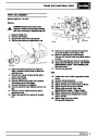
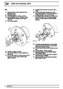
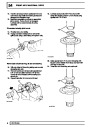
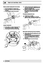
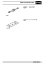
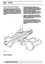
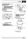
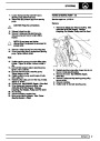
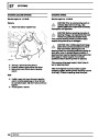
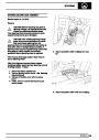
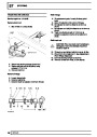
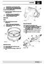
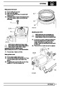
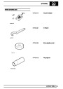
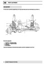
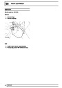
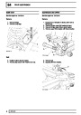
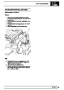
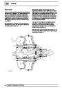
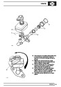
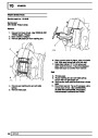
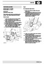
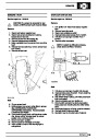
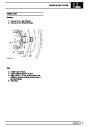
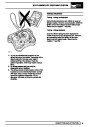
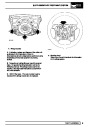
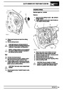
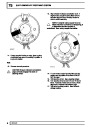
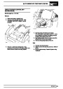
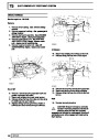
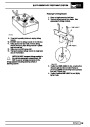
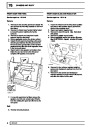
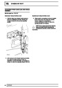
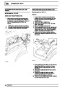
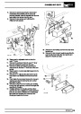
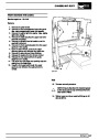
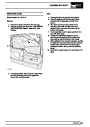
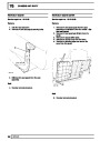
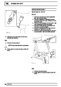
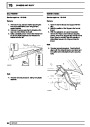
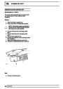
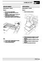
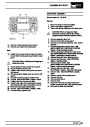
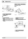
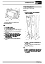
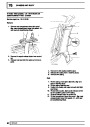
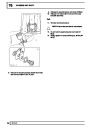
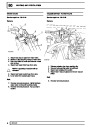
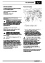
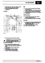
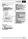
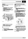
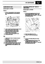
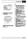
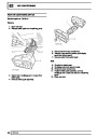
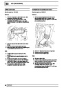
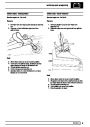
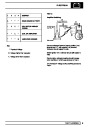
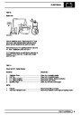
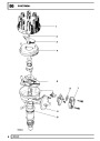
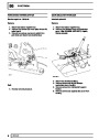
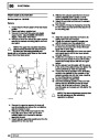
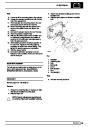
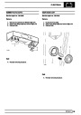
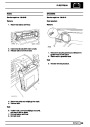
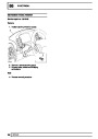
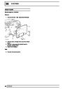
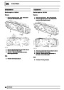
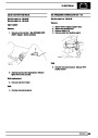
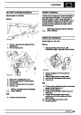
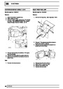
Camshaft position sensor (CMP Sensor)
The camshaft position sensor is located in the engine
front cover. It produces one pulse every two
revolutions. The signal is used in two areas, injector
timing corrections for fully sequential fuelling and
active knock control.
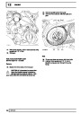
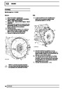
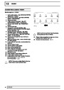
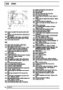
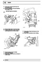
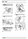
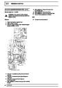
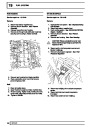
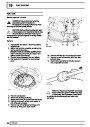
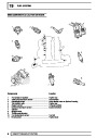
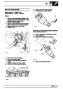
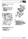
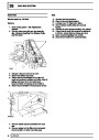
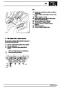
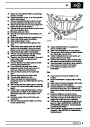
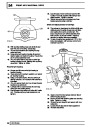
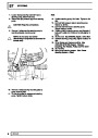
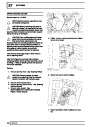
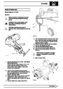
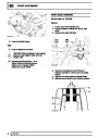
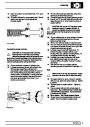
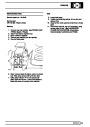
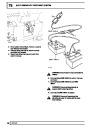
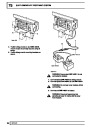
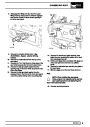
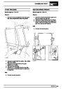
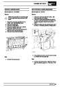
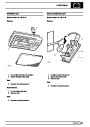
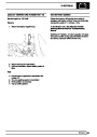
The ignition system does not use a distributor. It is a
direct ignition system (DIS), using four double ended
coils. The circuit to each coil is completed by
switching inside the ECM.
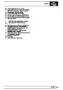
The on board diagnostic system detects any faults
which may occur within the EMS. Fault diagnosis
includes failure of all EMS sensors and actuators,
emissions related items, fuel supply and exhaust
systems.
If the camshaft sensor fails, default operation is to
continue normal ignition timing. The fuel injectors will
be actuated sequentially, timing the injection with
respect to top dead centre. Injection will either be
correct or one revolution out of synchronisation. The
fault is not easily detected by the driver. The fault is
indicated by illumination of the malfunction indicator
light (MIL) on North American specification vehicles.
The system incorporates certain default strategies to
enable the vehicle to be driven in case of sensor
failure. This may mean that a fault is not detected by
the driver. The fault is indicated by illumination of the
malfunction indicator light (MIL) on North American
specification vehicles.
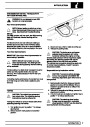
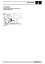
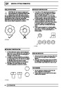
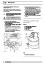
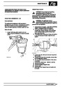
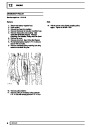
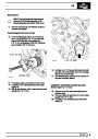
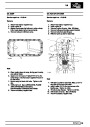
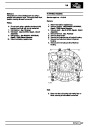
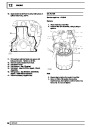
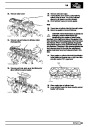
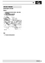
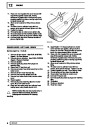
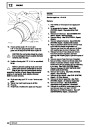
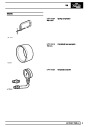
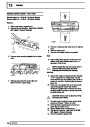
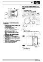
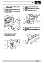
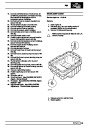
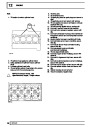
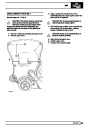
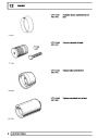
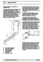
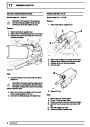
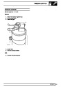
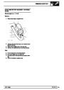
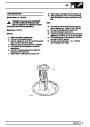
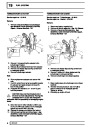
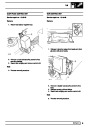
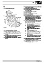
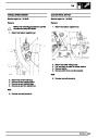
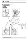
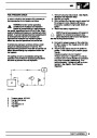
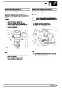
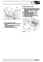
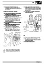
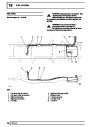
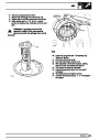
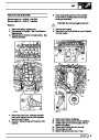
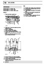
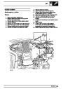
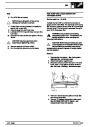
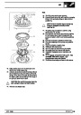
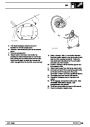
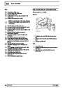
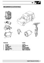
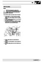
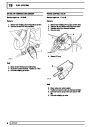
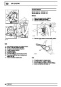
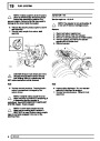
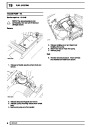
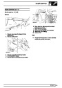
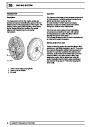
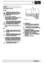
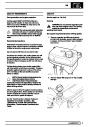
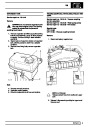
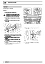
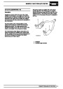
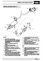
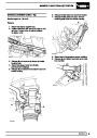
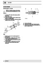
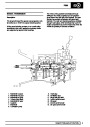
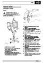
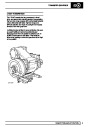
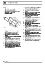
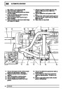
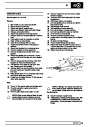
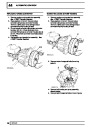
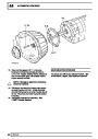
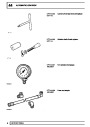
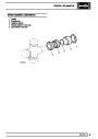
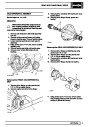
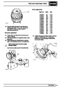
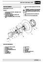
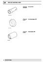
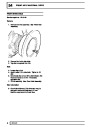
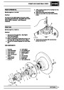
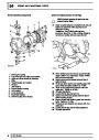
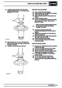
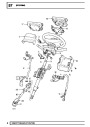
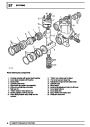
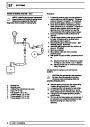
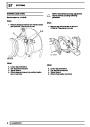
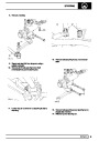
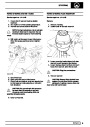
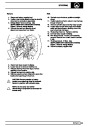
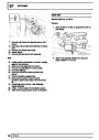
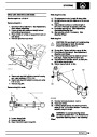
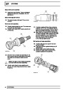
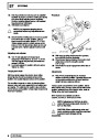
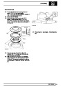
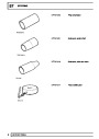
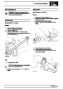
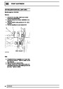
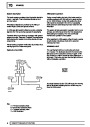
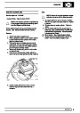
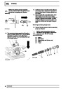
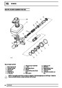
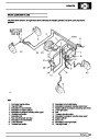
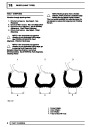
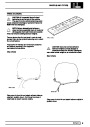
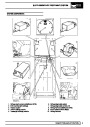
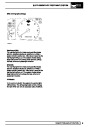
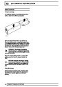
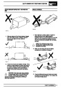
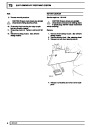
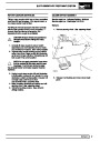
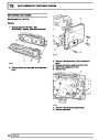
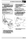
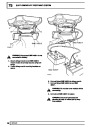
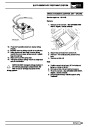
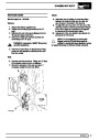
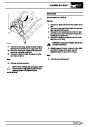
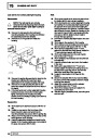
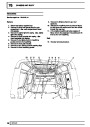
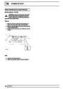
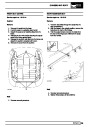
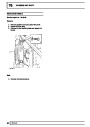
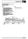
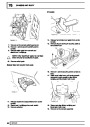
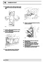
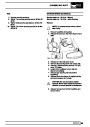
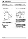
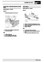
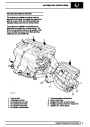
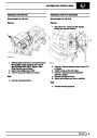
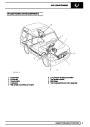
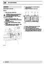
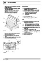
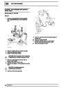
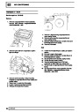
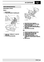
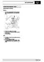
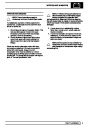
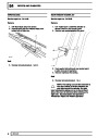
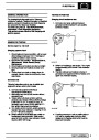
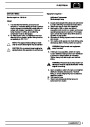
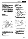
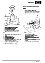
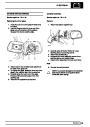
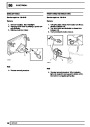
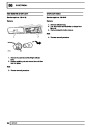
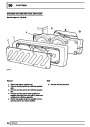
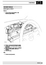
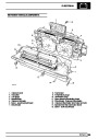
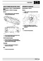
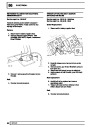
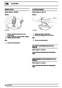
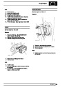
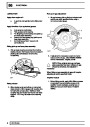
Mass air flow sensor (MAF Sensor)
The ’hot wire’ type mass air flow sensor is mounted
rigidly to the air filter and connected by flexible hose to
the plenum chamber inlet. The sensing element of the
MAF Sensor is a hot wire anenometer consisting of
two wires, a sensing wire which is heated and a
compensating wire which is not heated. Air flows
across the wires cooling the heated one, changing its
resistance. The ECM measures this change in
resistance and calculates the amount of air flowing
into the engine.
A further feature of the system is ’robust
immobilisation’.
As there is no default strategy, failure will result in the
engine starting, and dying when it reaches 550
rev/min, when the ECM detects no MAF Sensor
signal. The fault is indicated by illumination of the
malfunction indicator light (MIL) on North American
specification vehicles.
DESCRIPTION AND OPERATION
1
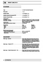
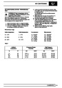
| Categories | Range Rover |
|---|---|
| Tags | Land Rover |
| Model Year | 1998 |
| Download File |
|
| Document Type | Workshop Manual |
| Language | English |
| Product Brand | Land Rover |
| Document File Type | |
| Publisher | landrover.com |
| Wikipedia's Page | http://en.wikipedia.org/wiki/Land_Rover |
| Copyright | Attribution Non-commercial |
(0 votes, average: 0 out of 5)