


19
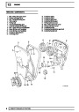
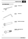
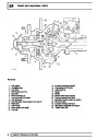
FUEL SYSTEM
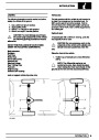
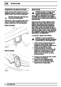
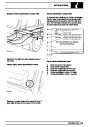
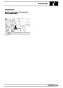
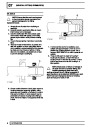
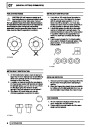
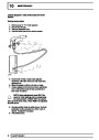
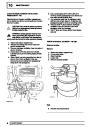
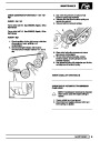
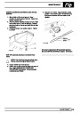
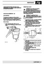
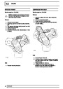
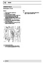
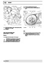
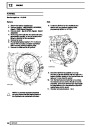
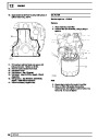
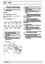
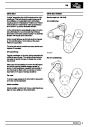
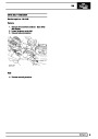
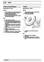
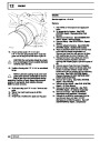
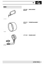
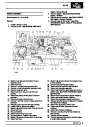
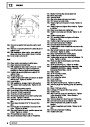
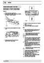
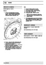
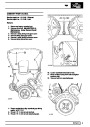
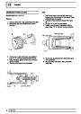
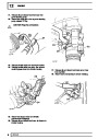
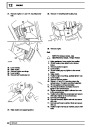
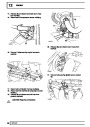
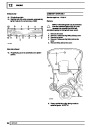
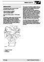
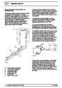
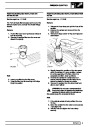
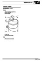
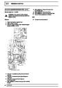
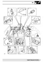
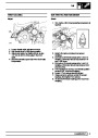
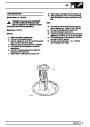
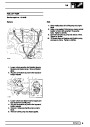
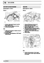
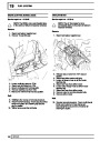
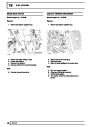
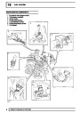
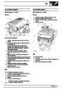
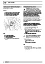
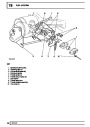
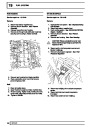
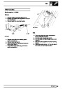
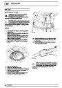
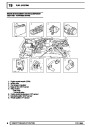
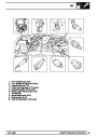
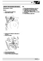
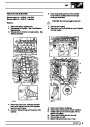
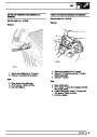
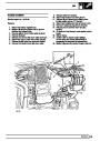
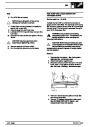
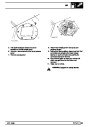
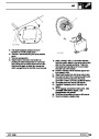
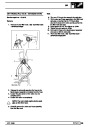
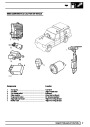
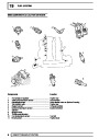
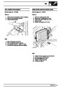
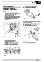
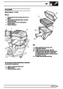
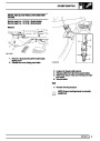
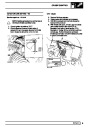
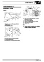
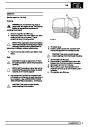
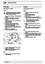
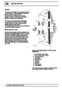
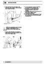
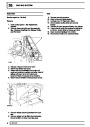
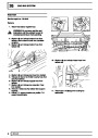
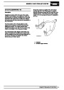
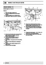
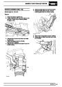
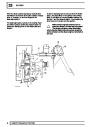
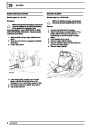
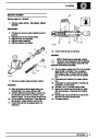
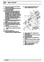
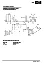
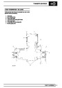
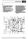
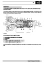
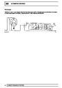
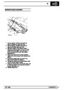
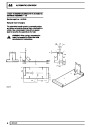
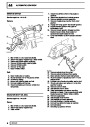
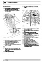
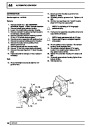
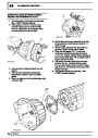
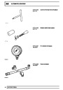
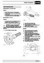
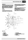
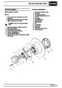
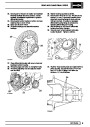
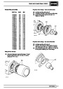
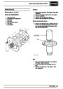
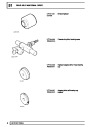
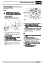
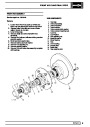
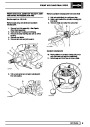
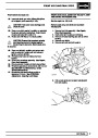
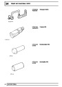
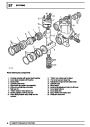
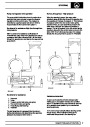
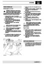
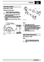
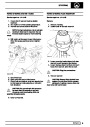
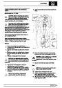
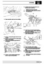
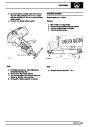
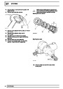
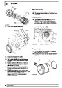
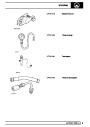
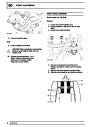
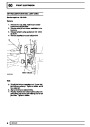
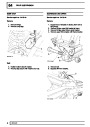
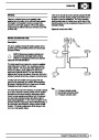
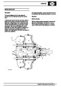
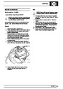
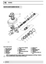
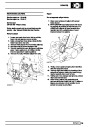
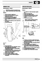
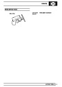
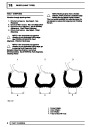
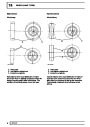
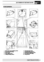
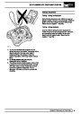
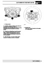
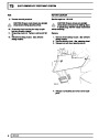
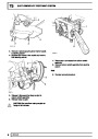
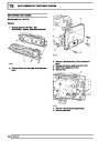
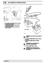
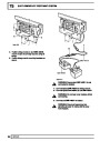
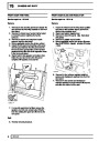
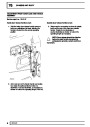
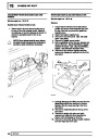
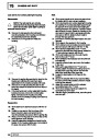
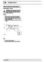
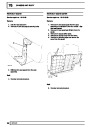
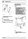
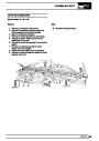
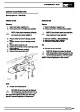
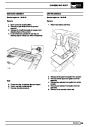
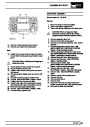
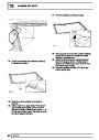
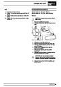
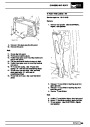
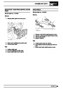
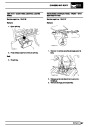
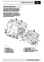
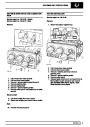
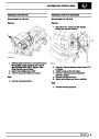
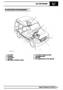
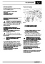
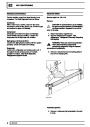
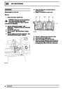
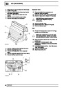
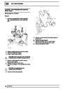
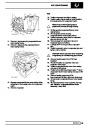
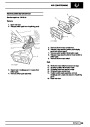
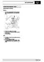
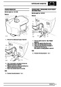
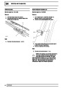
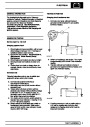
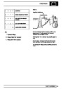
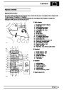
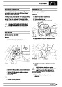
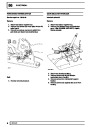
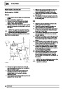
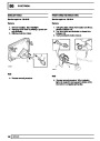
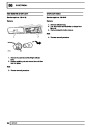
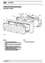
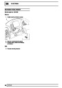
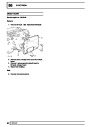
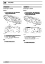
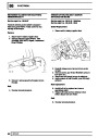
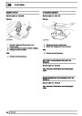
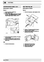
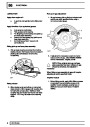
Fuel pressure regulator
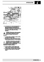
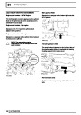
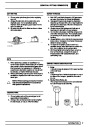
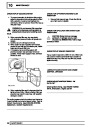
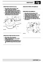
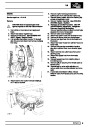
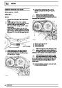
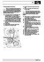
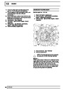
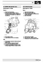
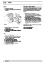
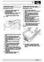
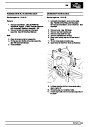
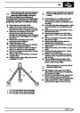
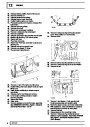
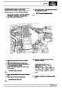
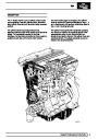
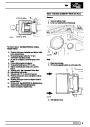
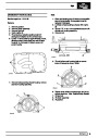
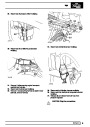
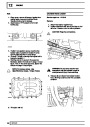
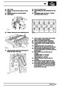
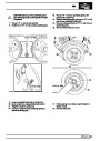
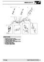
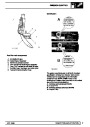
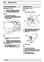
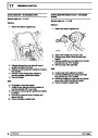
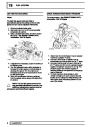
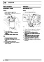
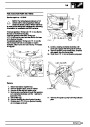
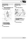
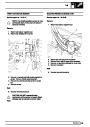
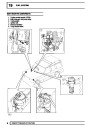
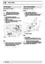
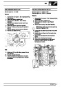
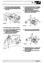
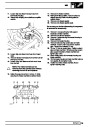
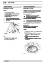
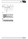
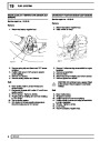
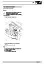
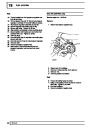
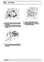
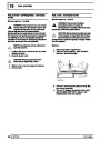
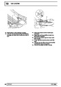
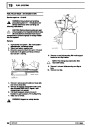
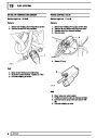
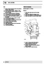
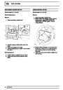
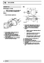
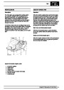
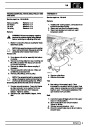
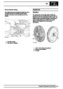
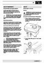
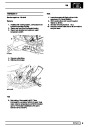
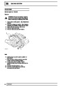
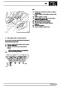
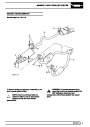
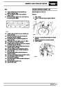
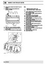
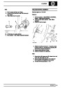
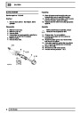
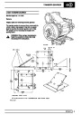
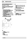
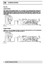
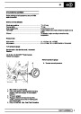
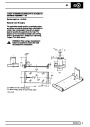
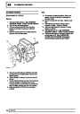
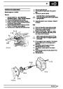
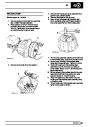
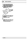
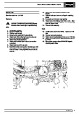
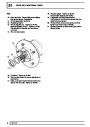
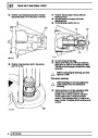
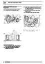
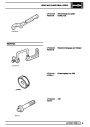
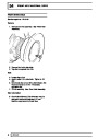
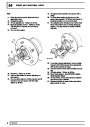
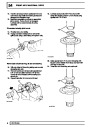
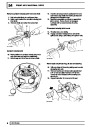
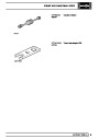
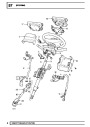
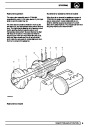
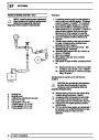
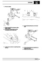
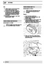
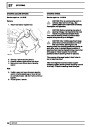
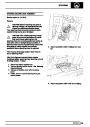
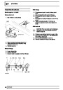
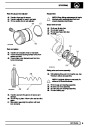
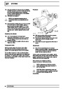
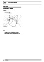
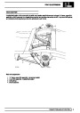
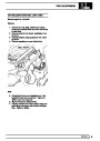
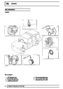
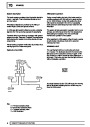
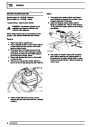
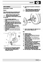
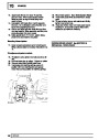
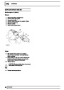
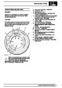
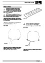
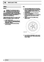
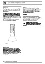
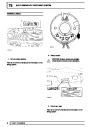
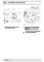
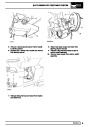
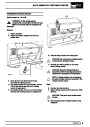
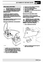
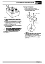
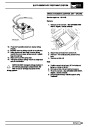
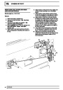
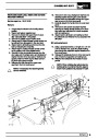
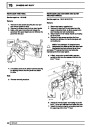
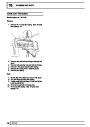
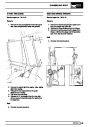
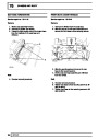
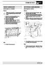
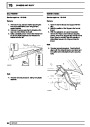
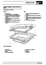
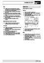
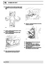
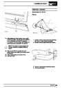
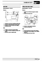
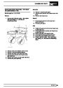
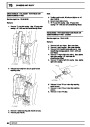
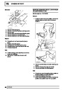
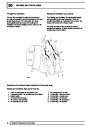
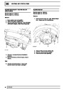
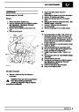
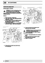
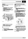
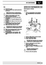
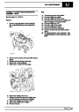
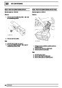
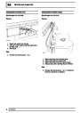
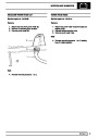
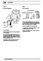
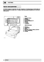
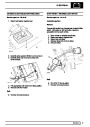
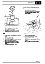
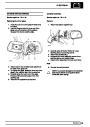
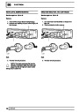
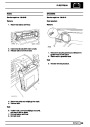
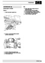
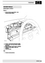
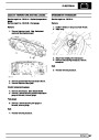
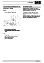
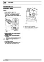
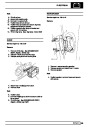
Throttle position sensor
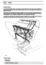
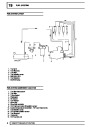
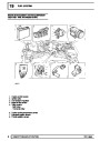
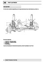
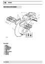
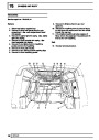
The fuel pressure regulator is mounted in the fuel rail
at the rear of the plenum chamber. The regulator is a
mechanical device controlled by plenum chamber
vacuum, it ensures that fuel rail pressure is
maintained at a constant pressure difference of 2.5
bar above that of the manifold.
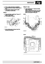
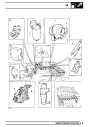
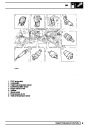
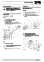
The throttle position sensor is mounted on the side of
the plenum chamber inlet neck and is directly coupled
to the throttle butterfly shaft.
The throttle position sensor is a resistive device
supplied with a voltage from the ECM. Movement of
the accelerator pedal causes the throttle valve to
open, thus rotating the wiper arm within the throttle
position sensor which in turn varies the resistance in
proportion to the valve position. The ECM lengthens
the injector open time when it detects a change in
output voltage (rising) from the throttle position
sensor.
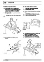
In addition the ECM will weaken the mixture when it
detects the throttle position sensor output voltage is
decreasing under deceleration and will shorten the
length of time the injectors are open.
When pressure exceeds the regulator setting excess
fuel is returned to the fuel tank.
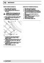
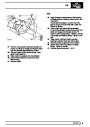
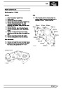
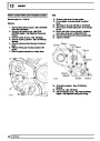
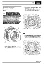
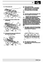
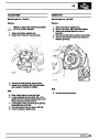
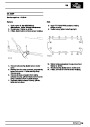
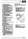
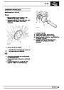
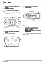
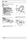
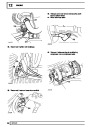
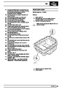
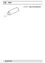
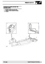
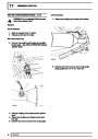
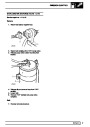
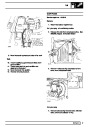
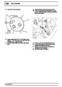
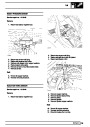
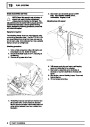
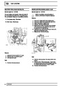
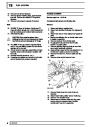
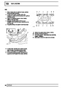
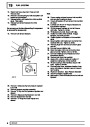
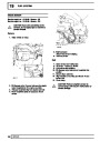
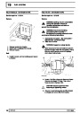
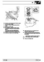
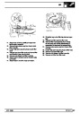
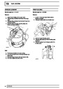
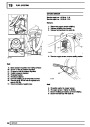
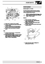
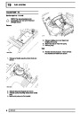
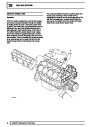
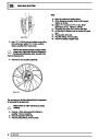
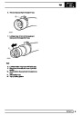
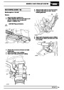
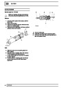
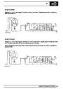
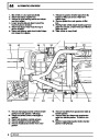
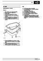
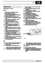
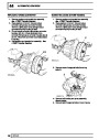
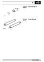
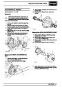
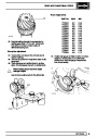
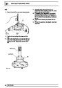
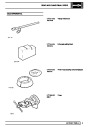
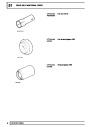
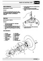
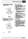
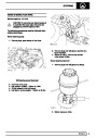
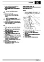
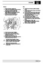
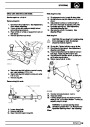
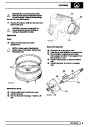
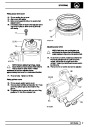
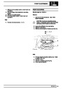
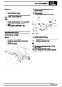
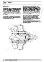
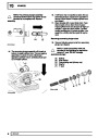
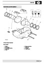
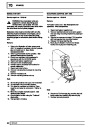
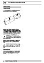
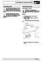
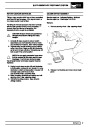
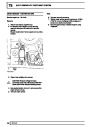
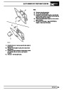
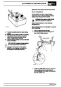
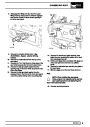
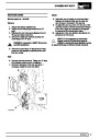
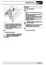
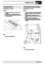
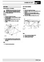
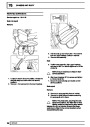
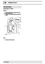
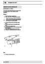
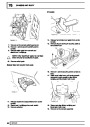
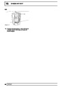
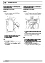
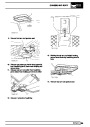
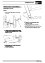
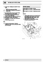
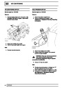
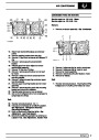
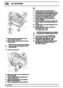
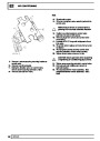
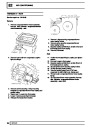
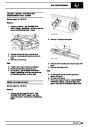
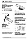
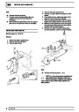
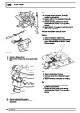
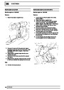
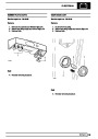
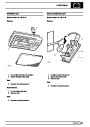
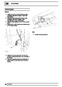
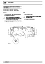
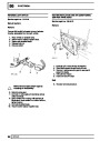
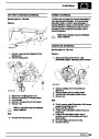
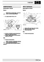
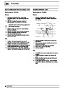
Fuel pump
The electric fuel pump is located in the fuel tank, and
is a self priming ’wet’ pump, the motor is immersed in
the fuel within the tank.
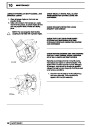
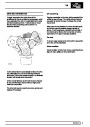
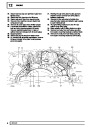
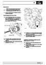
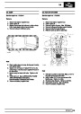
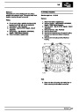
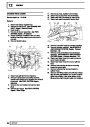
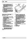
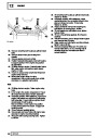
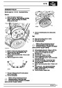
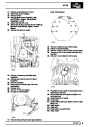
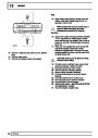
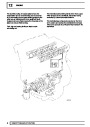
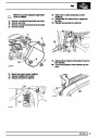
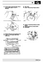
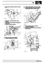
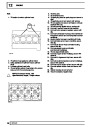
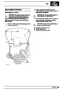
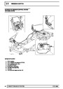
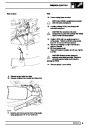
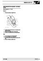
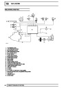
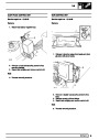
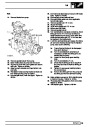
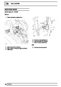
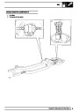
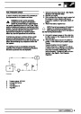
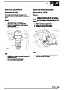
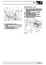
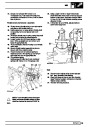
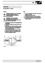
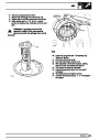
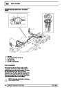
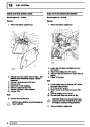
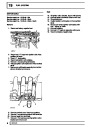
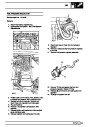
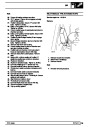
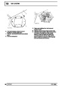
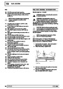
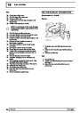
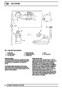
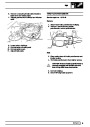
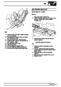
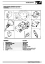
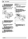
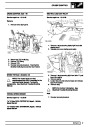
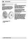
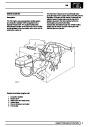
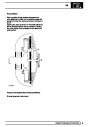
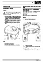
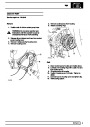
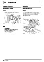
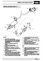
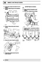
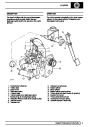
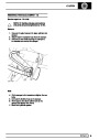
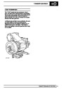
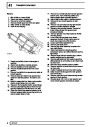
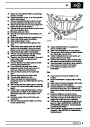
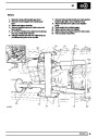
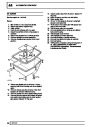
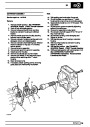
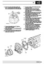
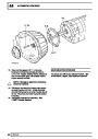
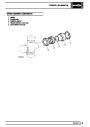
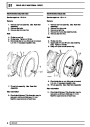
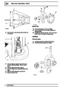
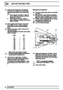
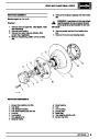
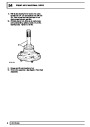
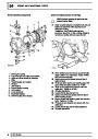
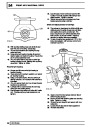
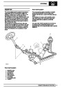
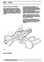
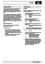
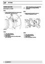
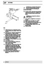
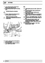
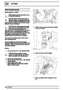
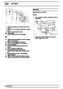
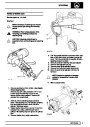
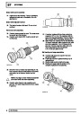
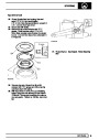
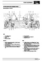
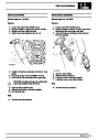
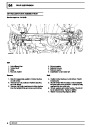
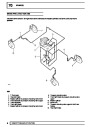
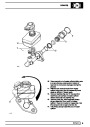
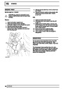
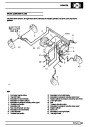
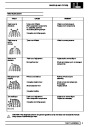
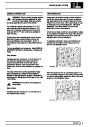
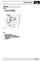
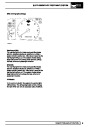
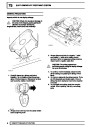
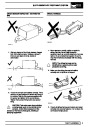
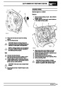
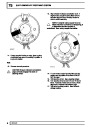
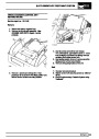
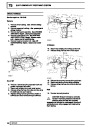
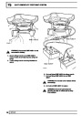
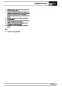
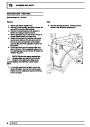
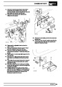
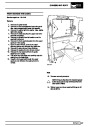
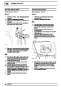
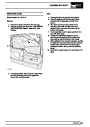
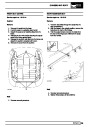
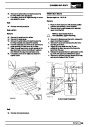
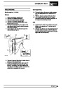
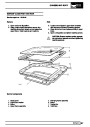
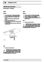
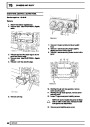
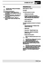
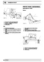
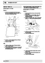
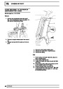
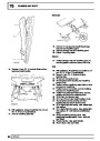
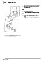
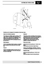
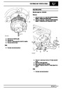
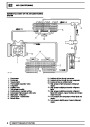
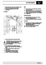
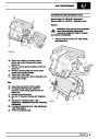
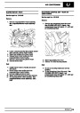
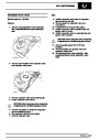
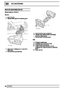
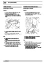
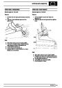
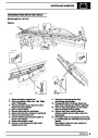
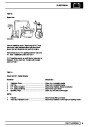
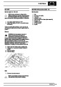
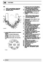
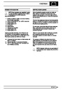
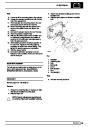
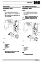
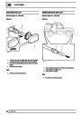
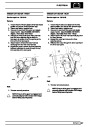
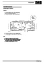
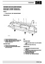
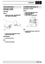
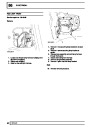
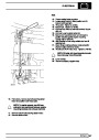
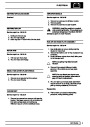
Air flow sensor
When the throttle is fully open, the ECM will detect the
corresponding throttle position sensor voltage and will
apply full load enrichment. This is a fixed percentage
and is independent of temperature. Full load
enrichment is also achieved by adjusting the length of
the injector open time.
When the throttle is closed, overrun fuel cut off or idle
speed control may be facilitated dependant on other
inputs to the ECM.
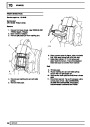
The throttle position sensor is ’self adaptive’, which
means that adjustment is not possible. It also means
the throttle position sensor setting is not lost, for
example, when throttle stop wear occurs.
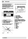
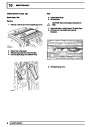
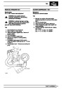
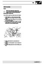
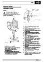
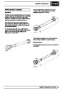
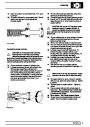
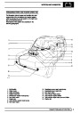
The hot-wire air flow sensor is mounted on a bracket
attached to the left hand valance, rigidly connected to
the air cleaner and by hose to the plenum chamber
inlet neck.
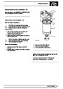
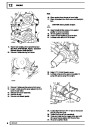
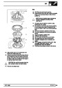
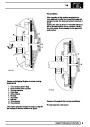
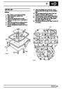
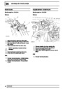
The air flow sensor consists of a cast alloy body
through which air flows. A proportion of this air flows
through a bypass in which two wire elements are
situated: one is a sensing wire and the other is a
compensating wire. Under the control of an electronic
module which is mounted on the air flow sensor body,
a small current is passed through the sensing wire to
produce a heating effect. The compensating wire is
also connected to the module but is not heated, but
reacts to the temperature of the air taken in, as engine
intake air passes over the wires a cooling effect takes
place.
CAUTION: Do not attempt to adjust throttle
position sensor.
The electronic module monitors the reaction of the
wires in proportion to the air stream and provides
output signals in proportion to the air mass flow rate
which are compatible with the requirements of the
ECM.
2
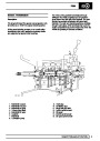
DESCRIPTION AND OPERATION
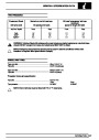
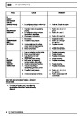
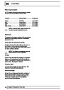
| Categories | Range Rover |
|---|---|
| Tags | Land Rover |
| Model Year | 1998 |
| Download File |
|
| Document Type | Workshop Manual |
| Language | English |
| Product Brand | Land Rover |
| Document File Type | |
| Publisher | landrover.com |
| Wikipedia's Page | http://en.wikipedia.org/wiki/Land_Rover |
| Copyright | Attribution Non-commercial |
(0 votes, average: 0 out of 5)