


19
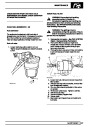
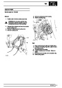
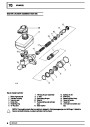
FUEL SYSTEM
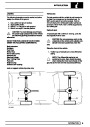
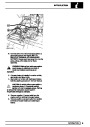
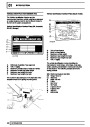
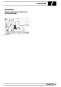
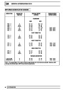
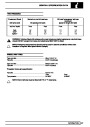
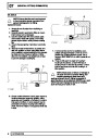
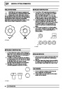
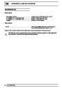
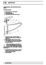
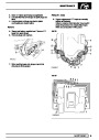
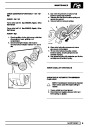
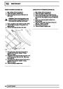
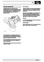
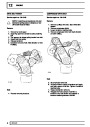
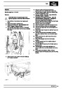
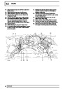
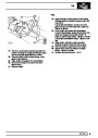
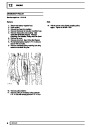
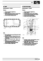
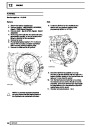
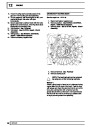
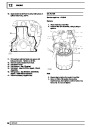
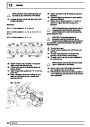
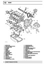
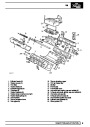
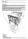
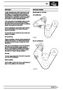
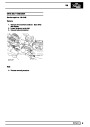
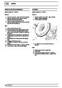
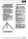
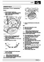
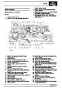
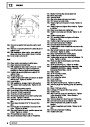
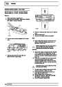
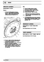
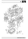
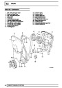
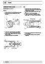
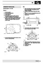
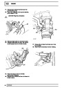
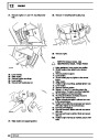
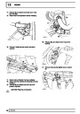
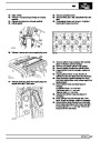
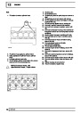
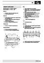
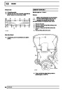
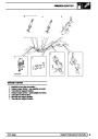
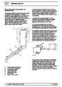
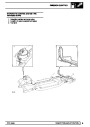
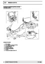
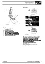
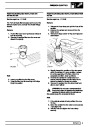
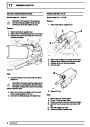
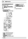
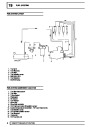
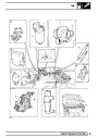
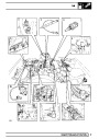
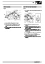
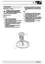
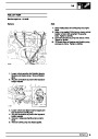
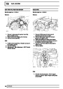
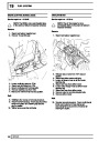
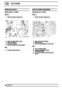
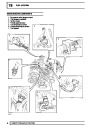
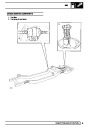
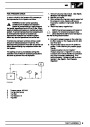
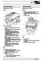
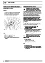
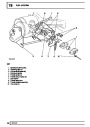
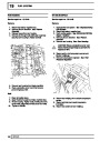
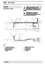
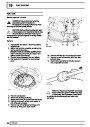
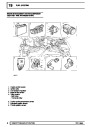
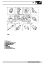
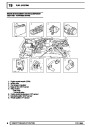
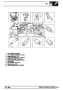
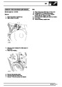
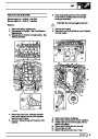
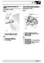
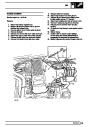
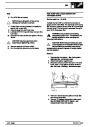
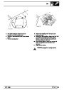
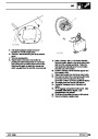
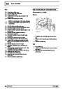
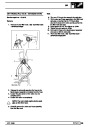
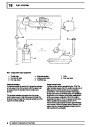
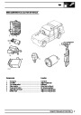
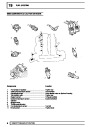
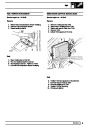
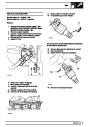
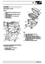
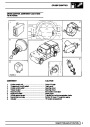
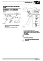
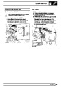
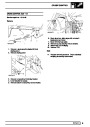
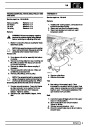
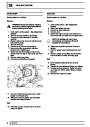
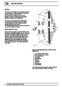
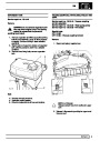
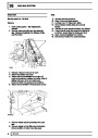
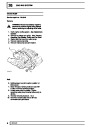
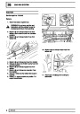
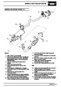
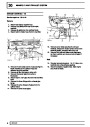
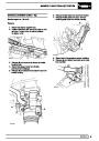
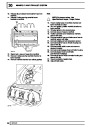
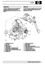
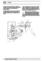
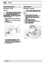
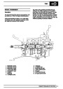
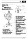
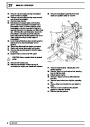
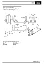
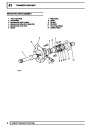
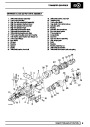
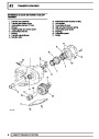
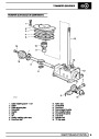
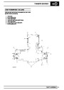
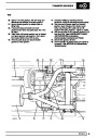
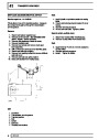
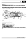
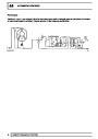
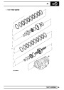
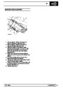
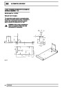
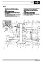
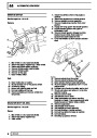
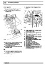
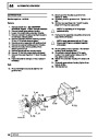
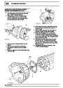
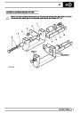
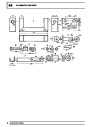
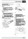
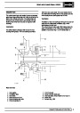
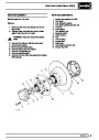
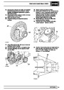
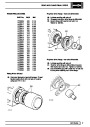
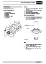
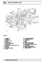
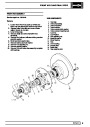
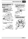
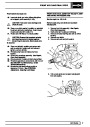
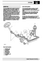
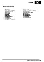
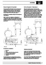
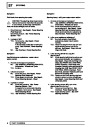
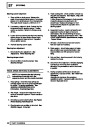
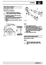
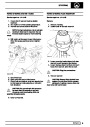
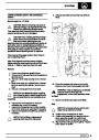
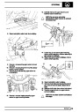
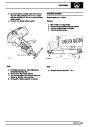
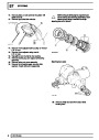
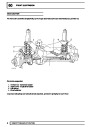
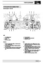
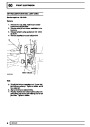
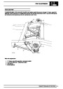
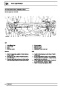
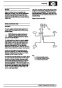
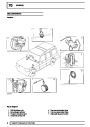
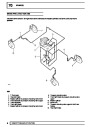
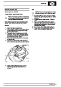
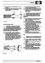
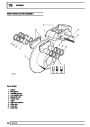
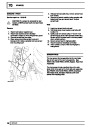
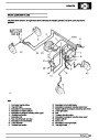
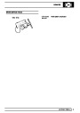
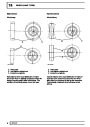
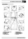
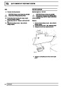
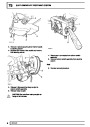
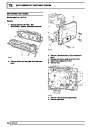
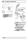
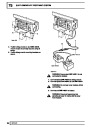
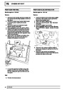
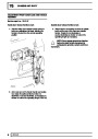
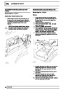
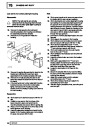
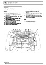
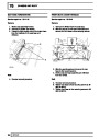
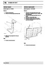
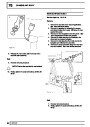
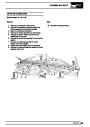
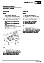
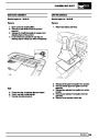
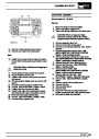
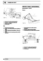
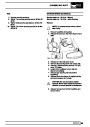
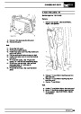
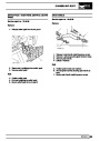
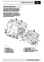
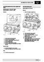
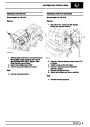
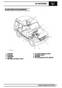
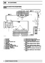
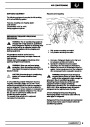
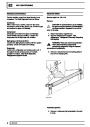
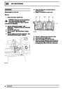
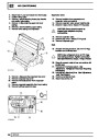
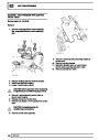
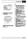
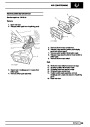
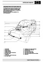
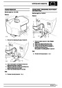
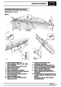
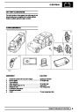
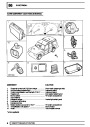
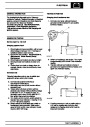
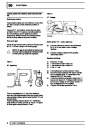
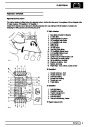
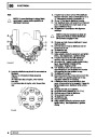
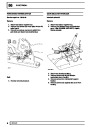
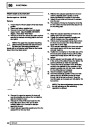
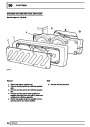
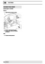
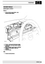
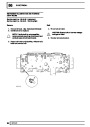
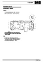
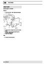
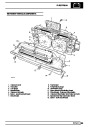
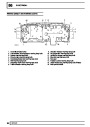
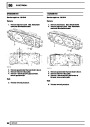
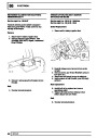
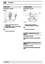
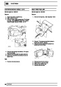
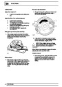
FUEL SYSTEM LAYOUT EDC
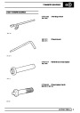
1.
2.
3.
4.
5.
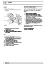
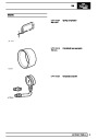
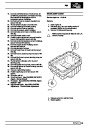
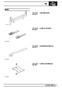
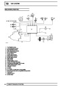
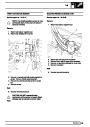
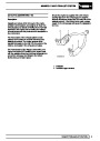
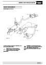
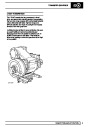
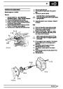
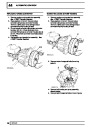
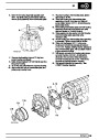
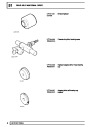
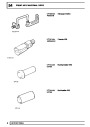
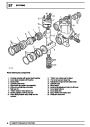
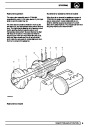
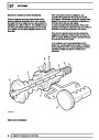
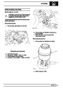
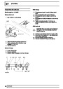
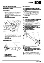
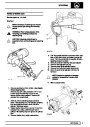
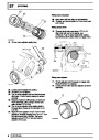
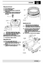
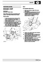
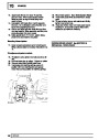
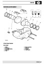
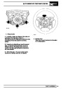
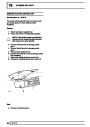
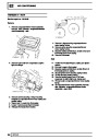
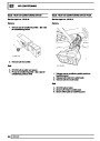
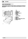
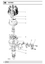
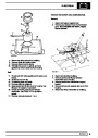
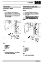
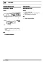
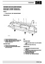
Fuel injection pump
Fuel temperature sensor
Air temperature sensor
Water temperature sensor
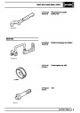
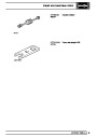
No. 4 injector sensor
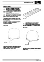
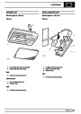
Air flow sensor
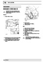
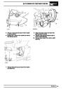
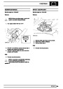
6.
7.
8.
9.
10.
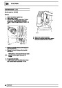
11.
12.
13.
14.
15.
16.
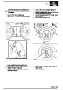
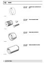
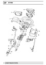
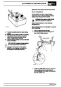
Engine speed sensor
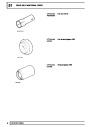
Boost pressure sensor
Vehicle speed sensor
Clutch switch
Brake switch
Throttle position sensor
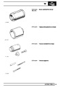
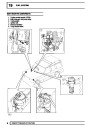
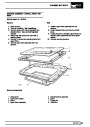
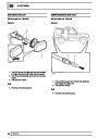
Electro-pneumatic modulator
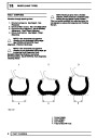
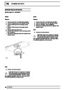
Exhaust gas recirculation (EGR) valve
Engine control module (ECM)
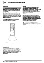
Diagnostic indicator
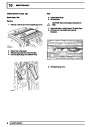
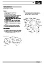
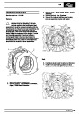
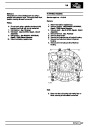
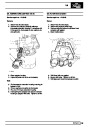
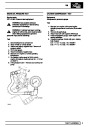
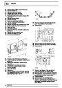
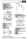
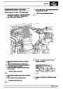
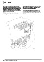
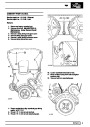
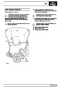
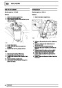
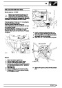
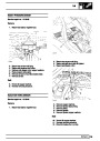
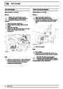
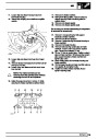
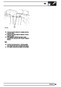
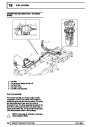
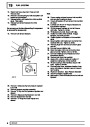
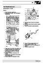
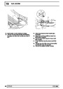
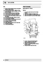
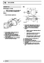
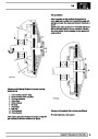
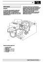
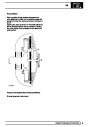
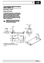
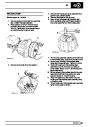
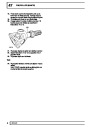
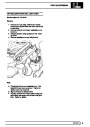
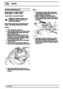
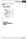
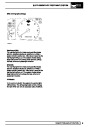
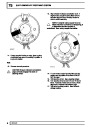
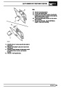
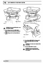
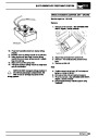
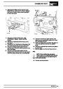
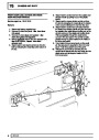
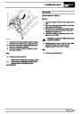
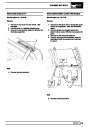
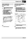
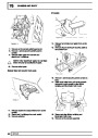
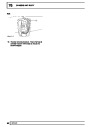
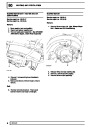
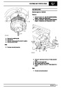
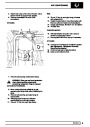
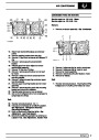
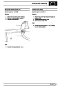
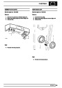
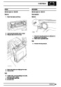
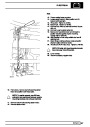
A. To turbo
B. To air box.
C. To ’T’ piece on brake servo hose position
D. Solenoid operated valve energization timing device.
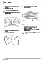
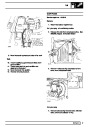
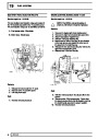
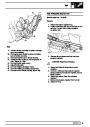
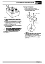
E. Fuel cut off
F. Actuator current
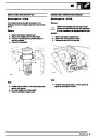
G. Control collar
8
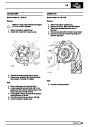
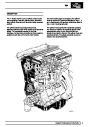
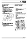
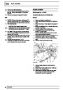
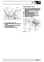
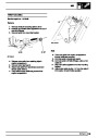
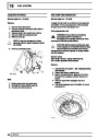
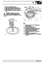
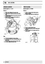
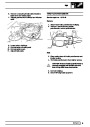
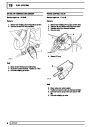
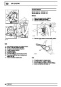
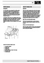
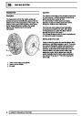
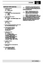
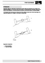
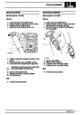
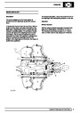
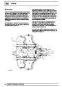
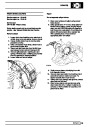
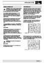
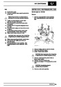
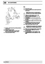
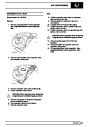
DESCRIPTION AND OPERATION
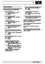
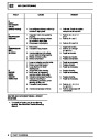
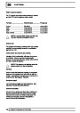
| Categories | Range Rover |
|---|---|
| Tags | Land Rover |
| Model Year | 1998 |
| Download File |
|
| Document Type | Workshop Manual |
| Language | English |
| Product Brand | Land Rover |
| Document File Type | |
| Publisher | landrover.com |
| Wikipedia's Page | http://en.wikipedia.org/wiki/Land_Rover |
| Copyright | Attribution Non-commercial |
(0 votes, average: 0 out of 5)