


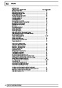


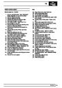


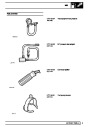


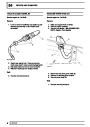


ABS
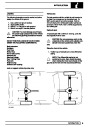
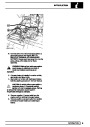
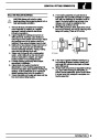
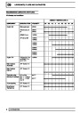
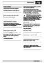
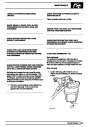
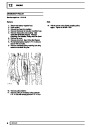
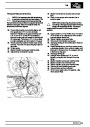
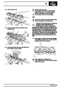
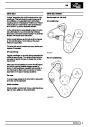
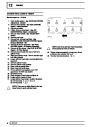
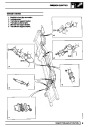
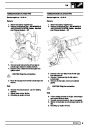
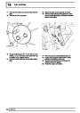
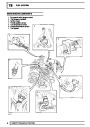
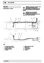
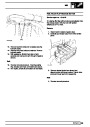
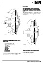
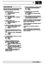
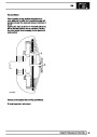
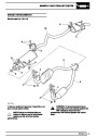
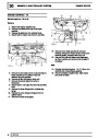
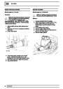
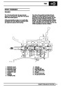
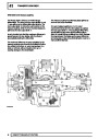
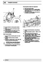
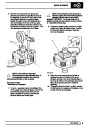
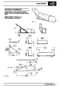
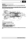
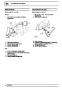
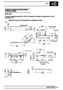
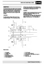
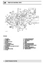
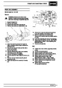
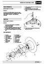
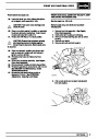
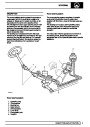
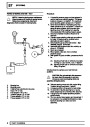
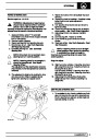
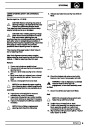
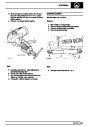
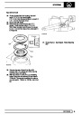
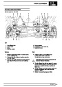
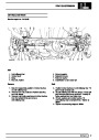
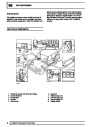
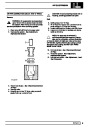
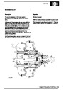
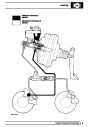
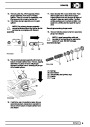
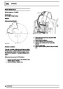
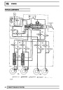
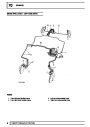
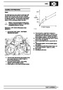
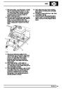
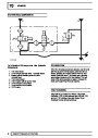
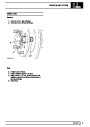
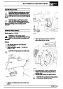
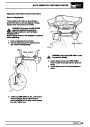
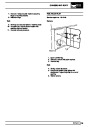
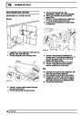
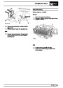
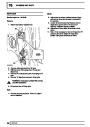
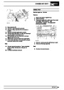
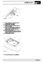
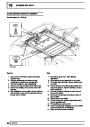
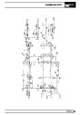
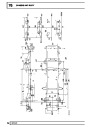
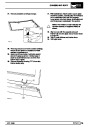
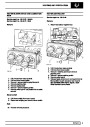
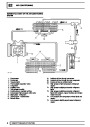
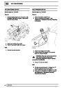
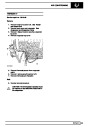
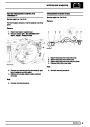
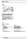
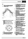
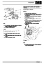
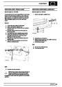
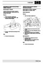
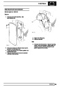
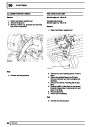
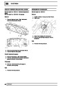
Hydraulic circuit - RR4076
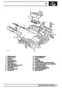
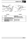
Key to diagram
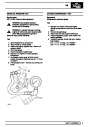
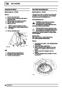
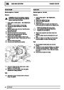
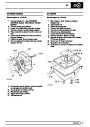
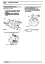
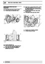
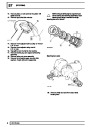
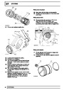
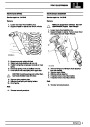
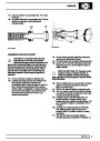
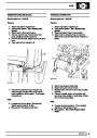
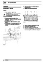
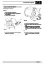
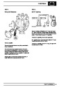
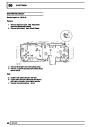
Master cylinder (1.3)
Operation of master cylinder displaces a volume of
brake fluid into servo cylinders and increases fluid
pressure. Piston movement inside master cylinder will
also activate power valve. A tilt valve is incorporated
to supply fluid to master cylinder from the reservoir
connection.
A Fluid feed/return
B Power circuit
C Hydrostatic (master cylinder) circuit
D Combined hydrostatic/power circuit
E Component enclosure
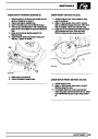
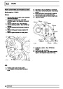
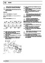
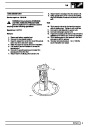
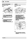
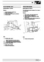
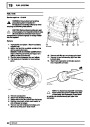
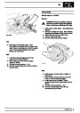
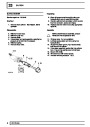
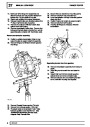
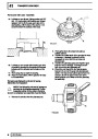
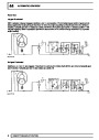
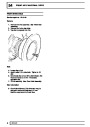
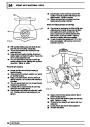
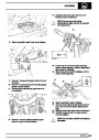
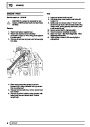
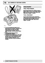
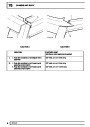
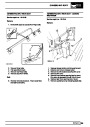
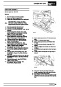
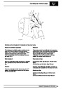
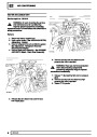
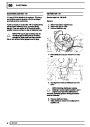
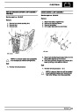
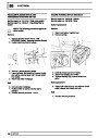
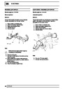
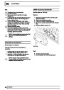
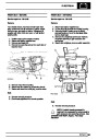
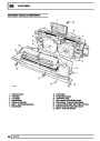
Isolating valve (1.4)
Hydraulic components
Isolating valve consists of two solenoid valves
controlling fluid inlet and outlet. Their function is to
disconnect master cylinder from servo cylinder and to
connect servo cylinder to reservoir return during ABS
function.
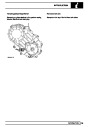
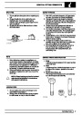
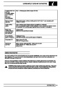
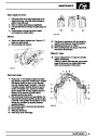
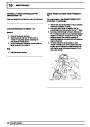
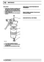
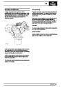
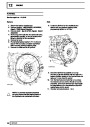
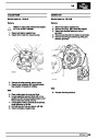
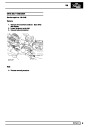
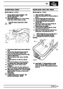
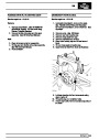
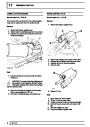
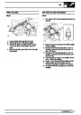
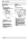
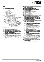
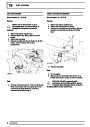
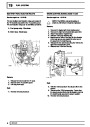
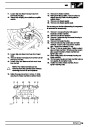
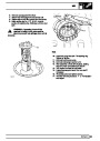
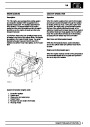
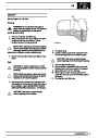
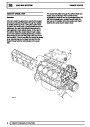
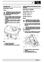
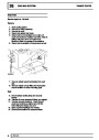
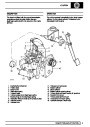
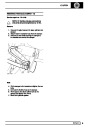
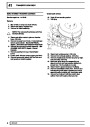
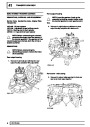
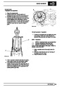
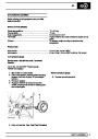
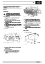
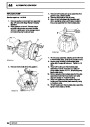
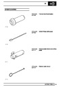
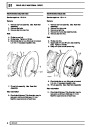
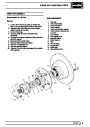
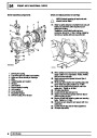
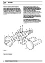
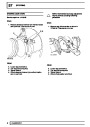
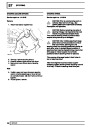
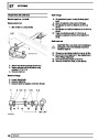
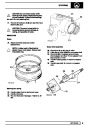
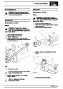
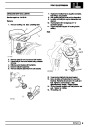
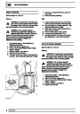
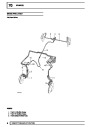
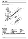
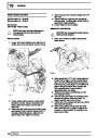
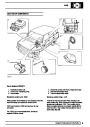
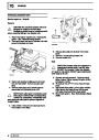
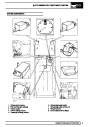
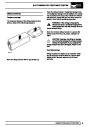
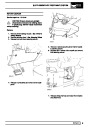
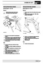
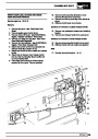
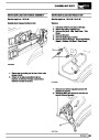
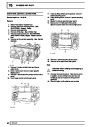
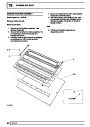
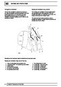
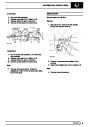
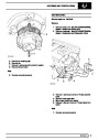
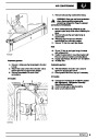
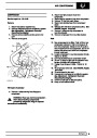
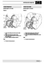
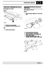
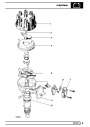
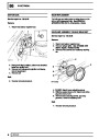
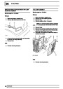
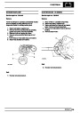
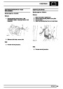
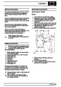
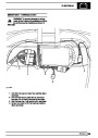
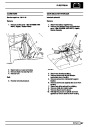
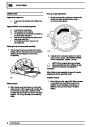
Hydraulic booster unit (1)
Mounted in same position as conventional master
cylinder/servo unit, booster unit contains following
components:
Fluid reservoir, power valve, master cylinder, isolating
valve, ABS solenoid control valves, servo cylinders.
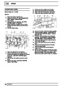
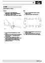
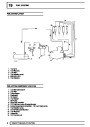
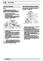
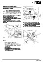
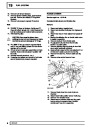
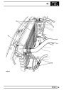
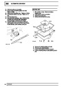
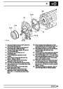
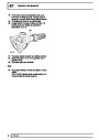
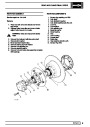
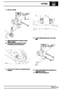
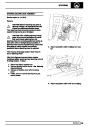
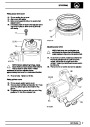
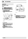
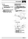
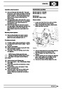
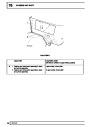
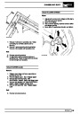
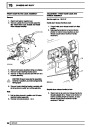
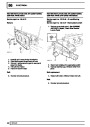
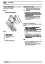
ABS solenoid control valves - 8 off (1.5)
Each pair, comprising inlet and outlet solenoid valves,
controls ABS braking to each wheel. In response to
signals from ECU, the valves decrease, hold or
increase brake pressure according to need to retain
wheel rotation and obtain optimum braking. The
solenoid valves are designed to respond rapidly to
ECU signals.
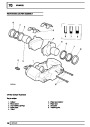
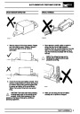
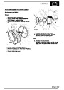
NOTE: Hydraulic booster unit is not a
serviceable item, if internal failure occurs
a new unit must be fitted. The fluid
reservoir and its seals may be changed in the
event of damage. Extreme care must be taken
when changing reservoir seals to avoid ingress of
debris.
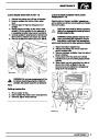
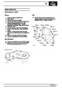
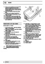
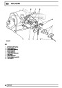
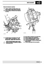
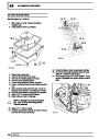
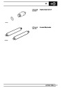
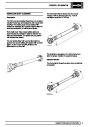
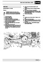
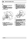
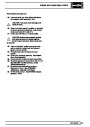
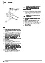
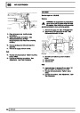
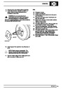
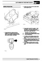
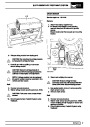
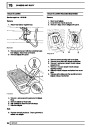
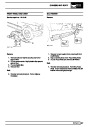
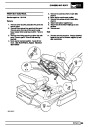
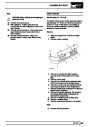
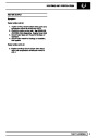
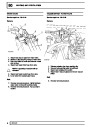
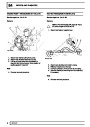
Servo cylinders - 2 off (1.6)
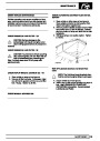
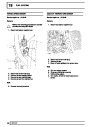
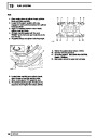
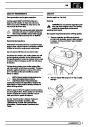
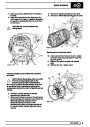
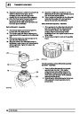
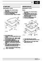
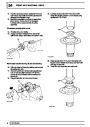
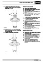
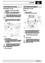
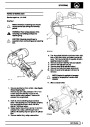
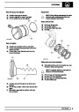
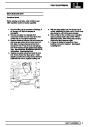
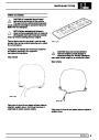
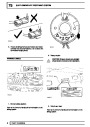
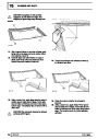
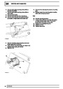
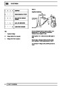
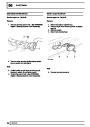
Fluid reservoir (1.1)
Servo cylinders have four functions:
Mounted on top of booster unit, the plastic reservoir is
subdivided internally to provide separate capacity for
brake fluid used in the hydrostatic and power circuits.
A central tube incorporates a filter and low fluid
warning level switch.
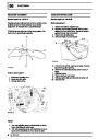
1. To provide combined energy from both
hydrostatic and power circuit to brake calipers.
2. To provide ’brake feel’ at brake pedal.
3. To provide hydrostatic (master cylinder) braking
through servo cylinder to calipers in event of no
power circuit pressure to servo cylinder.
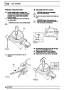
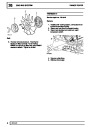
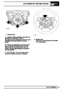
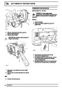
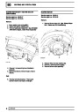
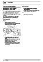
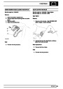
Power valve (1.2)
4.
To provide braking from both power circuit and
from hydrostatic fluid remaining in servo cylinder,
in event of no hydrostatic circuit pressure from
master cylinder.
The power valve is an extension of master cylinder, it
controls fluid pressure in power circuit in direct
proportion to pressure in master cylinder. Power valve
is of spool valve design.
DESCRIPTION AND OPERATION
3
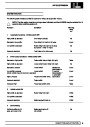
| Categories | Land Rover, Range Rover |
|---|---|
| Tags | Land Rover |
| Model Year | 1995 |
| Download File |
|
| Document Type | Owners Manual |
| Language | English |
| Product Name | Range Rover Classic |
| Product Brand | Land Rover |
| Document File Type | |
| Publisher | landrover.com |
| Wikipedia's Page | http://en.wikipedia.org/wiki/Land_Rover |
| Copyright | Attribution Non-commercial |
(0 votes, average: 0 out of 5)